


35
Reference Manual
00809-0100-4102, Rev AA
Section 3: Installation
May 2013
Installation
3.4 Installation procedures
For dimensional drawing information refer to Appendix A: Specifications and Reference Data on
page 89.
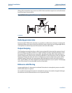
Process flange orientation
Mount the process flanges with sufficient clearance for process connections. For safety reasons,
place the drain/vent valves so the process fluid is directed away from possible human contact
when the vents are used. In addition, consider the need for a testing or calibration input.
Note
Most transmitters are calibrated in the horizontal position. Mounting the transmitter in any
other position will shift the zero point to the equivalent amount of liquid head pressure caused
by the varied mounting position. To reset zero point, refer to “Sensor Trim” on page 68.
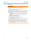
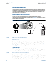
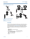
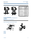
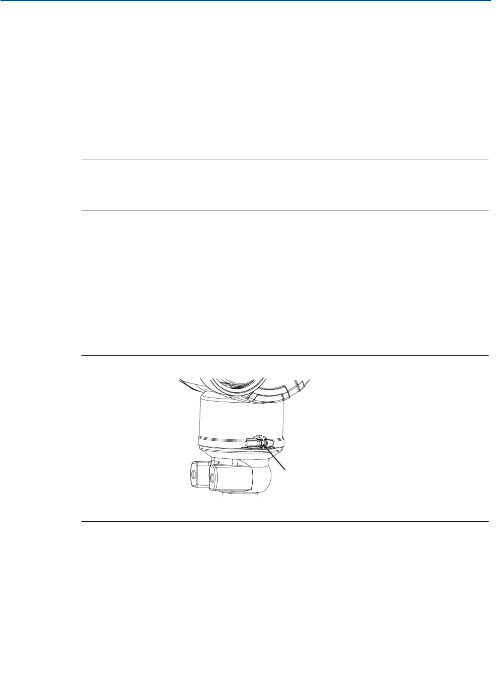
Consider housing rotation
The electronics housing can be rotated up to 180 degrees in either direction to improve field
access, or to better view the optional LCD Display. To rotate the housing, perform the following
procedure:
1. Loosen the housing rotation set screw using a -in. hex wrench.
2. Retighten the housing rotation set screw.
Figure 3-4. Housing rotation
A. Housing Rotation Set Screw (5/64-in.)
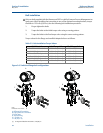
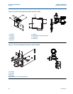
Power Module side of electronics housing
Mount the transmitter so the Power Module side is accessible. Clearance of 3.5-in. (89 mm) is
required for cover and Power Module removal.
Circuit side of electronics housing
Provide 1.75 in. (45 mm) of clearance for units without an LCD display. Three inches of clearance
is required for cover removal if a meter is installed.
5
64
------
A