3-9
VALVE CLEARANCE ADJUSTMENT
INSP
ADJ
NOTE:
*****************************************************
*****************************************************
YP303004
ENGINE
VALVE CLEARANCE ADJUSTMENT
Valve clearance adjustment should be made
with the engine cool, at room temperature.
When the valve clearance is to be measured or
adjusted, the piston must be at Top Dead Cen-
ter (T.D.C.) on the compression stroke.
1. Remove:
D Side panels
D Tail cover
D Fuel tank
Refer to “COVER AND PANEL” section.
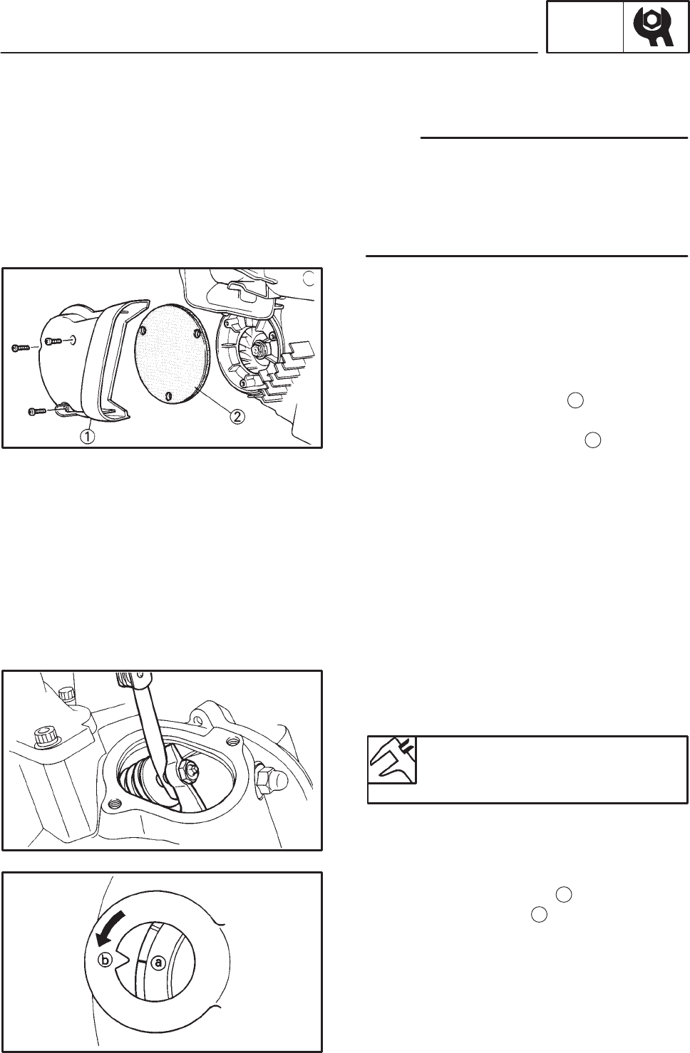
2. Remove:
D Crankcase filter cover
1
D Crankcase filter cover seal
D Crankcase filter element
2
3. Remove:
D Spark plug
D Valve cover (intake side)
D Valve cover (exhaust side)
4. Remove:
D Timing check plug
5. Measure:
D Valve clearance
Out of specification ! Adjust.
Valve clearance (cold):
Intake valve 0.08 0.12 mm
Exhaust valve 0.16 0.20 mm
Measurement steps:
D Rotate the primary fixed sheave counter-
clockwise to align the slit
a
on the rotor with
the stationary pointer
b
on the crankcover 1
when the piston is Top Dead Center (TDC).
D Measure the valve clearance by using a feel-
er gauge.
Out of specification ! Adjust clearance.


