


1-3
FEATURES
GEN
INFO
Main switch
Fuse
Battery
Thermo
switch
Auto-choke
Igniter unit
C.P.U
Ignition
Main switch
Engine stop switch
Brake
switch
Fuse
Starter relay
Relay
Ignitor unit
Battery
Starter
motor
Start
switch
Brake light
Sidestand
switch
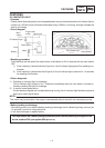
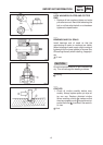
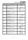
AUTO-CHOKE SYSTEM
This system is the parallel connection of the ignitor unit circuit and the thermo switch as shown, detect-
ing the engine temperature, and facilitates the restarting with the warm engine.
SCircuit diagram
SAuto-choke operation
Engine condition
Start with the
cold engine
Crank with the
cold engine
Crank with the
warm engine
Restart with the
warm engine
Thermo switch OFF OFF ON ON
Ignitor unit circuit OFF ON ON OFF
Auto-choke Activates Activates Not activate Not activate
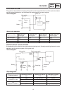
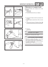
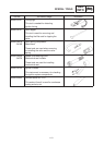
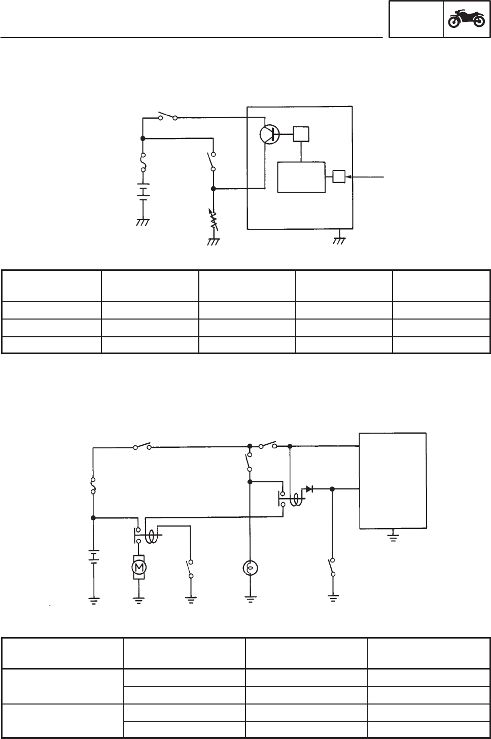
IGNITION CIRCUIT CUT-OFF SYSTEM
A sidestand circuit is added to the existing electric starting circuit, thereby controlling the starter motor
operation and the ignition system of the igniter unit.
SCircuit diagram
SOperating mode
Sidestand switch
Operation of brake
light
Operation of starter
motor
Operation of igniter
unit control
OFF
ON Not operated Misfire
(Sidestand in use)
OFF Not operated Misfire
ON
ON Operated Ignited
(Sidestand folded in)
OFF Not operated Ignited (ridden)