


2-21
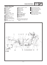
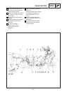
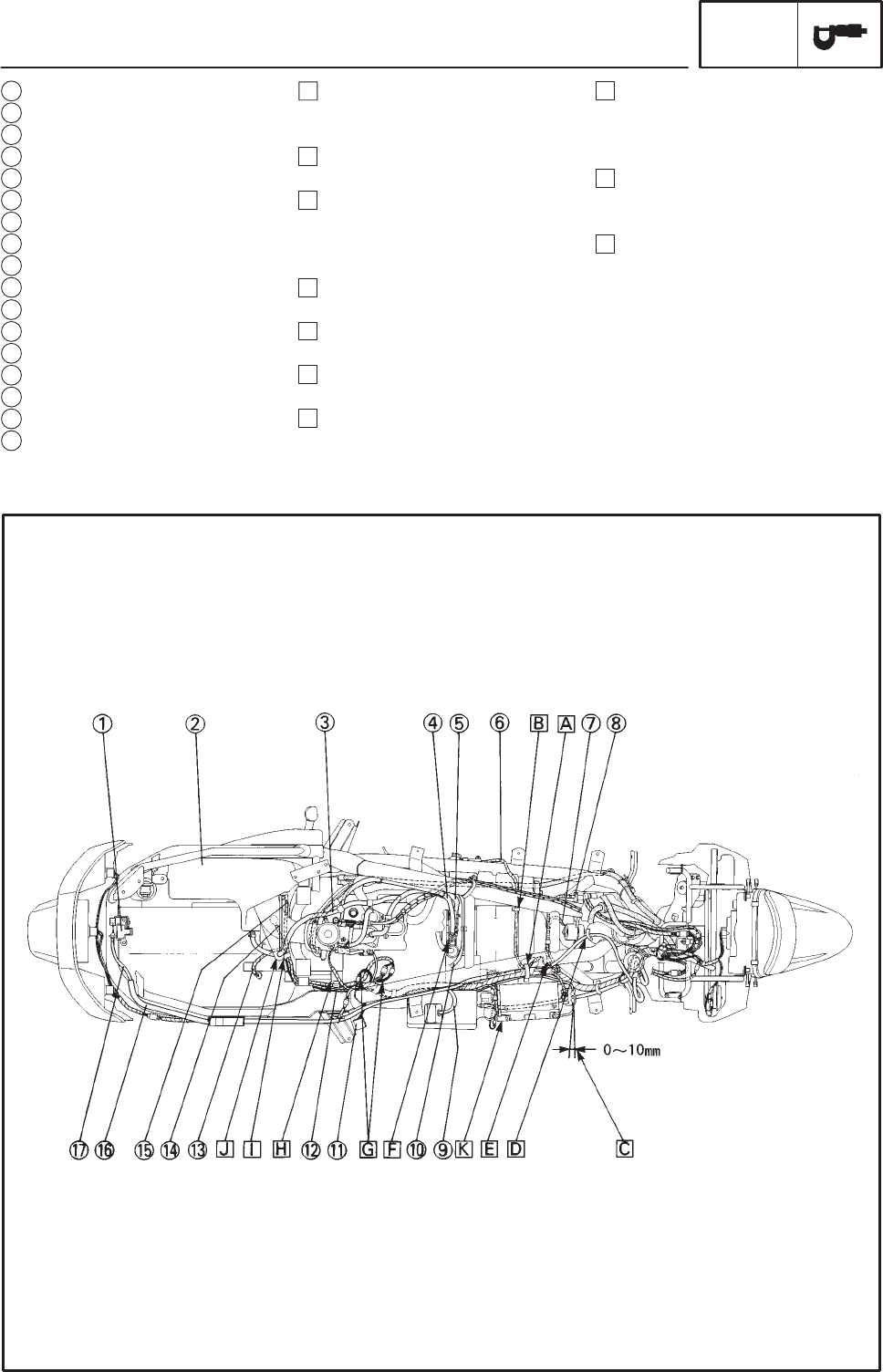
CABLE ROUTING
SPEC
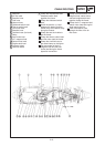
1 Seat lock
2 Air filter case
3 Breather hose
4 Fuel hose
5 Vacuum hose
6 Sidestand switch lead
7 Thermo switch lead
8 Fan motor lead ,
9 Breather hose
10 Overflow hose (fuel tank)
11 Relay
12 Auto choke lead
13 A.C. magneto lead
14 Starter motor lead
15 Engine earth lead
16 Protector (pipe)
17 Seat lock cable
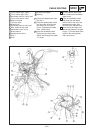
A Clamp the mainharness and
sidestand switch lead
together the frame.
B Clamp the sidestand switch
lead.
C Install the positive (+) lead
between the battery and the
starter relay to the starter relay
along the chassis.
D Clamp the seat lock cable to
the the frame.
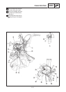
E Clamp the thermo switch lead
and fan motor lead the frame.
F Clamp the overflow hose to
the metal clamp on the frame.
G Put the coupler of the A.C.
magneto lead and the auto
choke lead along the frame
pipe after connection.
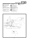
H Clamp the mainharness, A.C.
magneto lead, starter motor
lead and engine earth lead
together inside the frame.
I Clamp the A.C. magneto lead,
starter motor lead and engine
earth lead to the link.
J Pass the breather hose
through the hole of the air
filter case.