


8-32
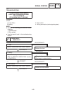
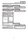
1. Bulb and bulb socket
Refer to “CHECKING SWITCHES” section.
Replace the bulb and/or bulb socket.
NO CONTINUITY
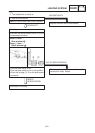
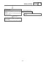
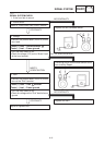
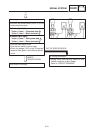
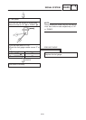
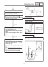
3. Voltage
S Connect the pocket tester (DC20 V) to the
bulb socket connector.
Tester (+) lead ! Blue terminal
Tester (–) lead ! Black terminal
S Turn the main switch to on.
S The brake lever is pulled in.
S Check for voltage (12 V) of the “Yellow” lead
on the bulb socket connector.
CONTINUITY
1
2
MEETS
SPECIFICATION
This circuit is not faulty.
OUT OF SPECIFICATION
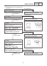
2. Brake switch (Front/Rear)
Refer to “CHECKING SWITCHES” section.
Replace brake switch.
NO CONTINUITY
CONTINUITY
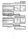
4. Wiring connection
S Wiring circuit from the main switch to the
bulb socket connector is faulty. Repair.
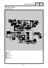
Refer to “SIGNAL SYSTEM WIRING DIA-
GRAM”.
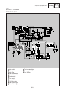
SIGNAL SYSTEM
ELEC
YP806022
2. If the brake light fails to come on: