


8-31
SIGNAL SYSTEM
ELEC
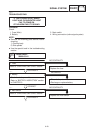
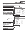
1. HORN switch
Refer to “CHECKING SWITCHES” section.
CONTINUITY
Replace the left handlebar switch.
NO CONTINUITY
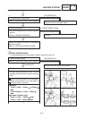
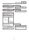
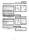
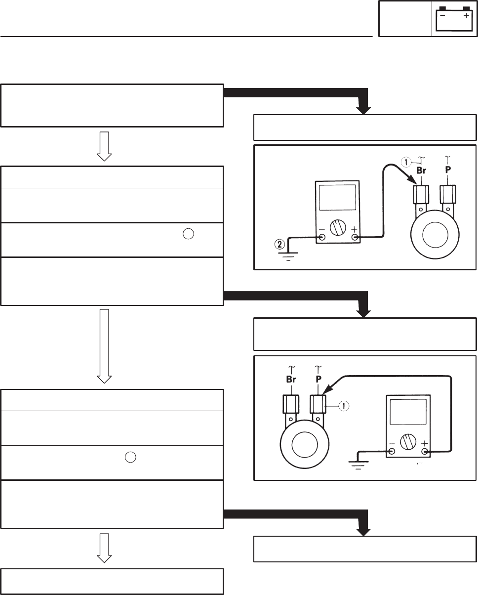
2. Voltage
S Connect the pocket tester (DC20 V) to the
horn lead.
Tester (+) lead ! Brown terminal .
Tester (–) lead ! Frame ground
1
MEETS
SPECIFICATION
S Turn the main switch to on.
S Check for voltage (12 V) on the “Brown” lead
at the horn terminal.
The wiring circuit from the main switch to the
horn is faulty. Repair.
OUT OF SPECIFICATION
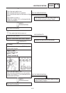
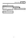
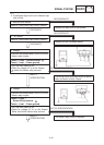
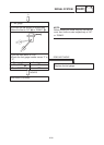
3. Horn
S Connect the pocket tester (DC20 V) to the
horn at the “Pink” terminal.
Tester (+) lead ! Pink terminal.
Tester (–) lead ! Frame ground
1
S Turn the main switch to on.
S Check for voltage on the “Pink” lead to frame
ground.
Replace the horn.
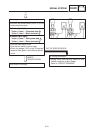
NO CONTINUITY
CONTINUITY
Adjust or replace horn.
YP806020
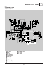
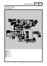
SIGNAL SYSTEM CHECK
1. If the horn fails to sound.