


2-22
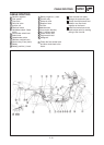
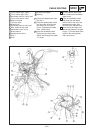
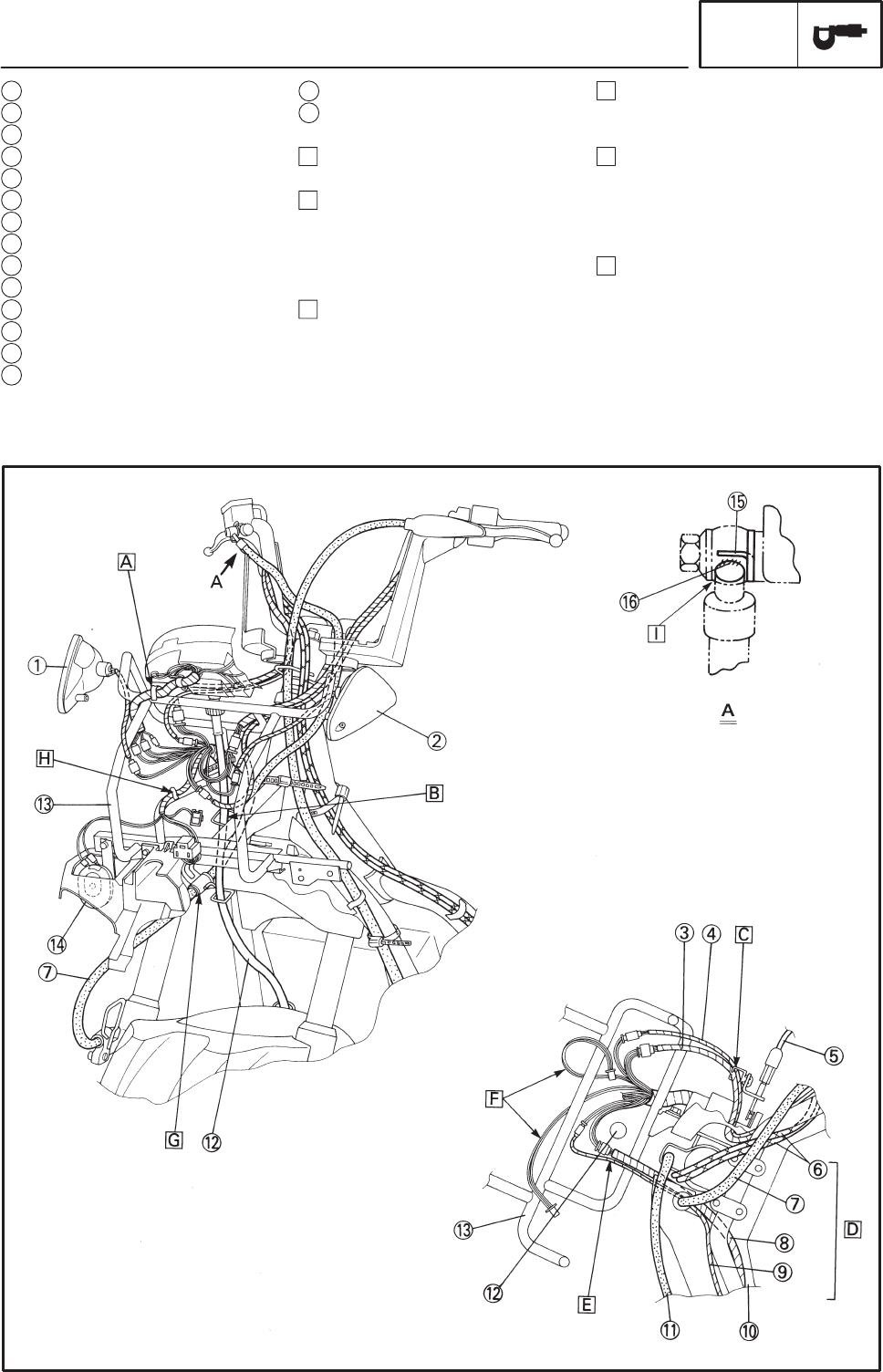
CABLE ROUTING
SPEC
1 Front flasher light (right)
2 Front flasher light (left)
3 Handlebar switch (right) lead
4 Front brake switch lead
5 Seat lock cable
6 Throttle cable
7 Brake hose
8 Handlebar switch (left) lead
9 Rear brake switch lead
10 Handlebar under cover
11 Brake cable 2
12 Speedometer cable
13 Stay 1
14 Horn
15 Brake hose stopper
16 Marking
A Clamp the speedometer lead
the stay 1.
B Pass the speedometer cable
and the brake hose through
the clamps on the frame.
(Front : Speedometer cable
Rear : Brake hose)
C Pass the handlebar switch
(right) lead and front brake
switch lead through the plastic
“U” clamp.
D Do not interfere each other
after installing the handlebar
upper cover.
E Pass the handlebar switch
(left) lead and rear brake
switch lead on the left of the
speedometer cable, then
connect to the mainharness.
F Hook the left and right front
flasher light leads on the pipe
of stay 1. (Put the leads down
inside of the cowling body
after connection.)