


8-35
SIGNAL SYSTEM
ELEC
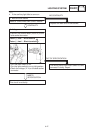
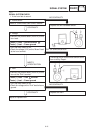
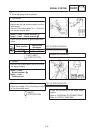
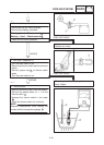
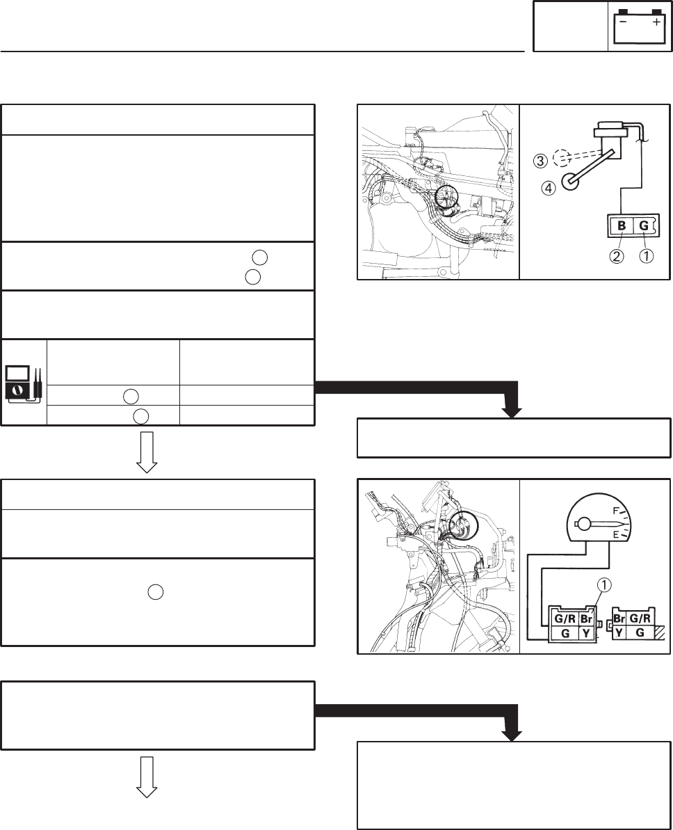
Float position
Specificated
resistance
UP 4 X 10 Ω
90 X 100 ΩDOWN
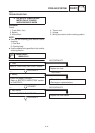
1. Fuel sender
S Remove the fuel sender from the fuel tank.
S Disconnect the fuel sender coupler from the
wireharness.
Connect the pocket tester (Ω 10) to the
fuel sender coupler lead.
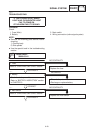
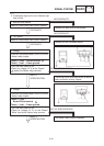
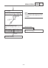
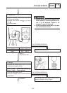
2. Voltage
S Connect the pocket tester (DC20 V) to the
fuel gauge coupler.
Tester (+) lead ! Green terminal
Tester (–) lead ! Black terminal
1
3
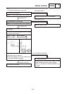
S Check the fuel sender for specificated resis-
tance.
Replace the fuel sender.
OUT OF SPECIFICATION
S Turn the main switch to “ON”.
S Check for voltage (12 V) of the “Brown” lead
on the fuel sender lead.
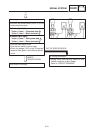
OUT OF SPECIFICATION
Check the connection of the entire signal
system.
Refer to “CHECKING OF CONNECTIONS”.
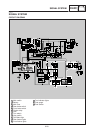
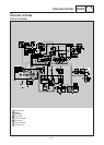
Refer to “CIRCUIT DIAGRAM”.
MEETS
SPECIFICATION
4
BOTH MEET
SPECIFICATION
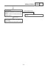
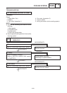
Tester (+) lead !
Brown terminal
Tester (–) lead !
Frame ground
1
:
2
YP806027
4. If the fuel gauge fails to operate.