


8-47
YP******
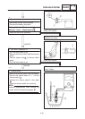
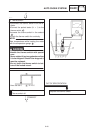
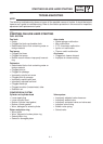
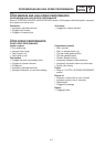
6. Auto choke unit resistance
S Disconnect the auto choke unit coupler from
the wireharness.
S Connect the pocket tester (Ω 1) to the
auto choke unit coupler lead.
:
Auto choke unit resistance:
16 X 24 Ω (20_C)
Tester (+) lead ! Black terminal
Tester (–) lead ! Black terminal
1
2
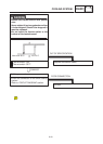
Replace the auto choke unit.
OUT OF SPECIFICATION
YP******
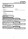
8. Wiring connection
S Check the connection of the entire auto
choke system.
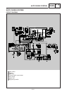
Refer to “CIRCUIT DIAGRAM” section.
POOR CONNECTION
Correct.
YP******
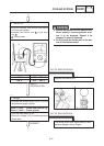
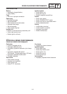
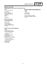
7. Voltage (temperature under 68_C)
S Connect the pocket teser (DC20 V) to the ig-
nitor unit.
Tester (+) lead !
Yellow/Red terminal (1 terminal)
Tester (–) lead ! Frame ground
1
Replace the ignitor unit.
OUT OF SPECIFICATION
S Turn the main switch to on, and start the en-
gine.
S Check for voltage (12 V) on “Yellow/Red”
terminal at the ignitor unit.
MEETS
SPECIFICATION
MEETS
SPECIFICATION
AUTO CHOKE SYSTEM
ELEC