


SECTION 12—MOTORS
Pronto® Series 118 Part No. 1125075
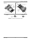
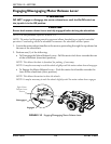
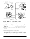
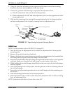
FIGURE 12.4 Replacing Motor Brushes
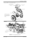
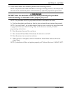
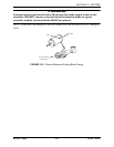
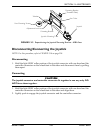
Electro-Mechanical Parking Brake Testing
NOTE: For this procedure, refer to FIGURE 12.5 on page 119.
NOTE: This procedure should only be performed on wheelchairs with conventional motor/gearbox
assembly.
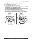
1. Engage the motor release lever. Refer to Engaging/Disengaging Motor Release Lever
on page 114.
2. On the four-pin motor connector, locate the side by side connectors in the black
housings.
3. Set the digital multimeter to read ohms.
4. Measure the resistance between the two brake contacts.
• A normal reading is between 45-100 ohms depending on the motor.
• A reading of 0 ohms (W) or a very high reading; i.e., MEG ohms or O.L. (out of
limit) indicates a shorted brake or an open connection respectively. If either
condition exists, send the motor to Invacare Technical Service for inspection/repair.
DETAIL “A” - REMOVE END CAP
DETAIL “B” - LOCATE MOTOR BRUSH
DETAIL “D” - REMOVE LARGE BRUSH
DETAIL “C” - REMOVE SHUNT WIRE
NOTE: Brush
assembly on one side
of Motor shown.
End Cap
End Cap Screws
2-Pole DC
Motor
Screwdriver to Remove
End Cap Screws (STEP 1)
Spring Retainer
Motor Brush
Brush Housing
Shunt Wire
Screwdriver to
Remove Shunt Wire
Screw
(STEP 4)
Motor Brush
Shunt Wire
Shunt Wire Mounting Screw
Screwdriver to Release Tension
on Spring Retainer (STEP 5)
Motor
Brush
Shunt
Wire
Spring Retainer