


SECTION 13—ELECTRONICS
Pronto® Series 122 Part No. 1125075
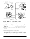
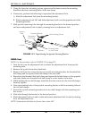
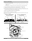
5. Using the three hex mounting screws, spacers and locknuts secure the mounting
bracket to the three mounting holes of the arm frame.
6. If necessary, perform the following to reposition the adjustment lock:
A. Slide the adjustment lock from the mounting bracket.
B. Rotate adjustment lock 180° and slide adjustment lock over the opposite end of the
mounting bracket.
7. Slide joystick mounting tube through the mounting bracket to the desired position
and secure adjustment lock to tube by turning lever on adjustment lock.
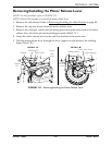
FIGURE 13.2 Repositioning the Joystick Mounting Bracket
ASBA Seat
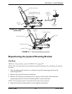
NOTE: For this procedure, refer to FIGURE 13.3 on page 123.
1. Turn the lever on the adjustment lock to release the adjustment lock from joystick
mounting tube.
2. Remove the joystick from the wheelchair.
3. Remove the three hex screws that secure joystick mounting bracket, the threaded hole
half clamp and the opened hole half clamp to the arm tube.
4. Reposition the threaded hole half clamp and opened hole half clamp on the opposite
arm tube. Make sure threaded hole half clamp is on the inside of arm tube.
5. While holding the two half clamps, install the front hex screw into the two half clamps.
Securely tighten.
6. Line up mounting holes of the joystick mounting bracket with the mounting holes in
the two half clamps.
7. Secure the joystick mounting bracket to the two half clamps with the remaining two
hex screws.
8. Slide tube through the bracket to the desired position.
9. Slide adjustment lock over end of tube and secure adjustment lock to tube by turning
lever on adjustment lock.
NOTE: If adjustment lock does not fit over tube, rotate 180°.
Hex Mounting Screws
Locknuts
Adjustment
Lock Lever
Mounting Bracket
Armrest
Plate
Spacers
Mounting Holes
on Arm Frame