


SECTION 9—WHEELS
Pronto® Series 84 Part No. 1125075
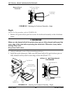
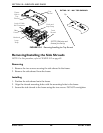
Removing/Installing the Drive Wheel
NOTE: For this procedure, refer to FIGURE 9.4 on page 85.
Removing the Drive Wheel
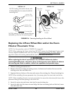
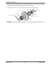
1. Fold down tab of existing locking tab washer (Detail “A” of FIGURE 9.4).
2. Remove mounting bolt and locking tab washer (Detail “B” of FIGURE 9.4). Discard
existing locking tab washer.
3. Remove the wheel from the drive shaft. If necessary, use wheel puller to remove the
drive wheel from the drive shaft.
Installing the Drive Wheel
NOTE: Ensure keystock is in the cutout on the drive shaft (Detail “B” of FIGURE 9.4). The
keystock MUST line up with the wheel hub cutout.
CAUTION
DO NOT apply more than a one-inch (in length) thin film of anti-seize compound to
the drive shaft. Applying more than one-inch (in length) can cause the anti-seize
compound to leak resulting in damage to flooring (carpet, tile, etc.).
1. Apply an anti-seize compound to drive shaft and keystock.
2. Align the keystock in the drive shaft with the cutout in the wheel hub and position the
wheel on to the drive shaft (Detail “B” of FIGURE 9.4).
ƽ WARNING
Failure to properly install locking tab washer can result in wheel separation and
potential user injury or property damage. When replacing wheels ALWAYS use a
new locking tab washer. DO NOT reuse locking tab washers.
NOTE: The locking tab of the locking tab washer MUST be inserted into the cutout in the rim and
hub (Detail “B” of FIGURE 9.4).
3. Using the mounting bolt, washer and new locking tab washer, secure the wheel to the
drive shaft (Detail “B” of FIGURE 9.4).
4. Fold one tab of the locking tab washer up so that the tab rests against one side of the
mounting bolt (Detail “A” of FIGURE 9.4)