


SECTION 3—SAFETY INSPECTION/TROUBLESHOOTING
Part No. 1125075 31 Pronto® Series
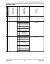
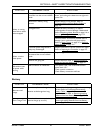
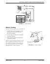
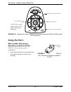
FIGURE 3.1 Field Load Test
Motor Testing
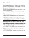
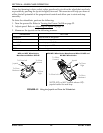
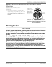
NOTE: For this procedure, refer to FIGURE 3.2.
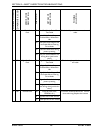
1. On the 4-pin motor connector, locate
the two contacts in the RED and
BLACK housings.
2. Set the digital multimeter to measure
resistance (ohms).
3. Measure the resistance between the
two motor contacts.
NOTE: A normal reading is between .5 and 5
ohms. A reading of 0 ohms or in excess of 15
ohms indicates a problem. High readings are
generally caused by bad connections and/or
damaged brushes. Contact Invacare.
FIGURE 3.2 Motor Testing
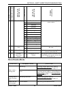
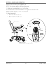
Charger
Port
Digital
Voltmeter
BATTERY
QUALITY
0 to 2 volts Good
2 to 2.5 volts Poor
2.5 or more Bad
4 Pin Motor
Connector
Motor
Cap