


Instruction Manual
IB-106-340 Rev. 2.4
April, 2001
Rosemount Analytical Inc. A Division of Emerson Process Management Troubleshooting 7-1
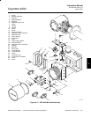
Oxymitter 4000
SECTION 7
TROUBLESHOOTING
Install all protective equipment covers
and safety ground leads after trouble-
shooting. Failure to install covers and
ground leads could result in serious
injury or death.
7-1 GENERAL
The troubleshooting section describes how to
identify and isolate faults that may develop in the
Oxymitter 4000. Also, additional troubleshooting
information is provided in paragraph 7-5 for those
units with the optional SPS 4000. When trouble-
shooting the Oxymitter 4000, reference the fol-
lowing information.
a. Grounding
It is essential that adequate grounding pre-
cautions are taken when installing the sys-
tem. Thoroughly check both the probe and
electronics to ensure the grounding quality
has not degraded during fault finding. The
system provides facilities for 100% effective
grounding and the total elimination of ground
loops.
b. Electrical Noise
The Oxymitter 4000 has been designed to
operate in the type of environment normally
found in a boiler room or control room.
Noise suppression circuits are employed on
all field terminations and main inputs. When
fault finding, evaluate the electrical noise
being generated in the immediate circuitry
of a faulty system. Also, ensure all cable
shields are connected to earth.
c. Loose Integrated Circuits
The Oxymitter 4000 uses a microprocessor
and supporting integrated circuits (IC). If the
electronics are handled roughly during in-
stallation or located where subjected to se-
vere vibration, the ICs could work loose.
Before troubleshooting the system, ensure
all ICs are fully seated.
d. Electrostatic Discharge
Electrostatic discharge can damage the ICs
used in the electronics. Before removing or
handling the processor board or the ICs,
ensure you are at ground potential.
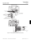
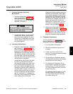
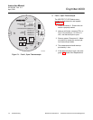
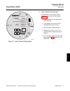
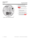
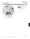
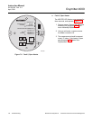
7-2 ALARM INDICATIONS
The majority of the fault conditions for the Oxy-
mitter 4000 will be indicated by one of the four
LEDs referred to as diagnostic, or unit, alarms
on the operator’s keypad. An LED will flash a
code that will correspond to an error message.
Only one LED will blink at a time. An alarm code
guide is provided inside the screw cover for the
electronics. All alarm indications will be avail-
able via the HART Model 275 handheld com-
municator and Rosemount’s Asset Management
software. When the error is corrected and/or
power is cycled, the diagnostic alarms will clear
or the next error on the priority list will appear.
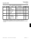
7-3 ALARM CONTACTS
a. If autocalibration is not utilized, a common
bi-directional logic contact is provided for
any of the diagnostic alarms listed in Table
7-1. The assignment of alarms which can
actuate this contact can be modified to one
of seven additional groupings listed in Table
5-1.
7