


Instruction Manual
IB-106-340 Rev. 2.4
April, 2001
Rosemount Analytical Inc. A Division of Emerson Process Management Maintenance and Service 6-11
Oxymitter 4000
3
D
3
96
1
9
G
REV
1
+
250VAC
TIME LAG
5A
+
+
+
+
+
+
+
+
1
FUSE
POWER
SUPPLY
BOARD
22220058
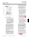
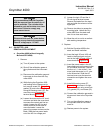
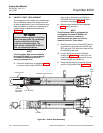
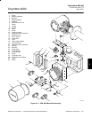
Figure 6-7. Fuse Location
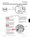
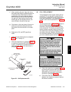
4. Squeeze the J8 connector on the sides
and carefully remove. The electronic
assembly can now be completely re-
moved from the housing.
5. Completely remove the three mounting
screws on the microprocessor board.
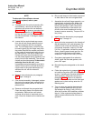
6. Turn the electronic assembly over so
that you are looking at the bottom of
the power supply printed circuit board.
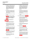
Gently depress the two white posts one
at a time. Carefully separate the power
supply board from the microprocessor
board.
7. Remove the fuse and replace it with a
new one (Figure 6-7).
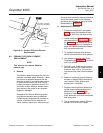
8. Align the white posts with the post
holes on the power supply board and
the pin connector on the power supply
board with the connector port on the
back of the microprocessor board.
Gently push the boards together until
the white posts snap in place. Ensure
the assembly is secure by gently trying
to separate the boards.
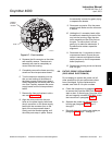
9. Reconnect connector J8 to the power
supply board. Make sure the connector
is secure.
10. Holding the J1 connector leads, slide
the electronic assembly the rest of the
way into the housing. Align the elec-
tronic assembly so that it fits flush on
the pins. To ensure that it is flush,
gently try to rotate the electronics. If
the electronics rotates, repeat the
alignment.
11. Reconnect the J1 connector to the mi-
croprocessor board. Ensure the con-
nector is secure and tighten the three
captive screws on the microprocessor
board (top board).
12. Replace the housing cover and ensure
that it is tight.
6-6 ENTIRE PROBE REPLACEMENT
(EXCLUDING ELECTRONICS)
Do not attempt to replace the probe until all
other possibilities for poor performance have
been considered. If probe replacement is
needed, see Table 8-1 for part numbers.
a. Follow the instructions in paragraph 6-4a.1
to remove the Oxymitter 4000 from the
stack or duct. If removing an Oxymitter 4000
with an integrally mounted SPS 4000, follow
the instructions in paragraph 6-4b.1.
b. Separate the probe and the electronics
housing per paragraph 6-5a, steps 2
through 6.
c. Reinstall electronics on the new probe per
paragraph 6-5a, steps 7 through 13.
6