


Instruction Manual
IB-106-340 Rev. 2.4
April, 2001
Rosemount Analytical Inc. A Division of Emerson Process Management Maintenance and Service 6-7
Oxymitter 4000
It is recommended that the Oxymitter
4000 be removed from the stack for all
service activities. The unit should be
allowed to cool and be taken to a clean
work area. Failure to comply may
cause severe burns.
Disconnect and lock out power before
working on any electrical components.
There is voltage up to 115 VAC.
6-4 OXYMITTER 4000
REMOVAL/REPLACEMENT
a. Oxymitter 4000 (without Integrally
Mounted SPS 4000)
1. Remove.
(a) Turn off power to the system.
(b) Shut off the calibration gases at
the cylinders and the instrument
air.
(c) Disconnect the calibration gas and
instrument air lines from the Oxy-
mitter 4000.
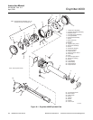
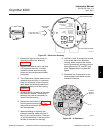
(d) While facing the Oxymitter 4000
and looking at the Rosemount la-
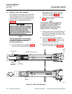
bel, remove screw (32, Figure 6-1),
gasket (33) and cover lock (34) se-
curing left housing cover (27). Re-
move the cover to expose the
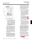
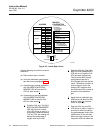
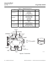
terminal block (Figure 6-4).
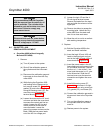
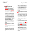
(e) Loosen the screw on the AC termi-
nal cover and slide the cover back
to access the neutral and line ter-
minals. Loosen the AC line and
neutral terminal screws and re-
move the leads. Loosen the
ground lug screws and remove the
leads. Slide the line power leads
out of the AC line voltage port.
(f) Loosen the logic I/O and the 4-
20 mA signal terminal screws.
Remove the leads from the termi-
nals and slide the wires out of the
signal port.
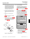
(g) Remove insulation to access the
mounting bolts. Unbolt the Oxy-
mitter 4000 from the stack and
take it to a clean work area.
(h) Allow the unit to cool to a comfort-
able working temperature.
2. Replace.
(a) Bolt the Oxymitter 4000 to the
stack and install insulation.
(b) Insert the logic I/O and 4-20 mA
leads in the signal port and con-
nect to the logic I/O and 4-20 mA
screw terminals (Figure 6-4).
(c) Insert the power leads in the AC
line voltage port and connect to the
AC line screw terminals. Connect
the line, or L1, wire to the L1 ter-
minal, and the neutral, or L2, wire
to the N terminal. Slide the AC
terminal cover over the terminal
connection and tighten the cover
screw.
(d) Install left housing cover (27,
Figure 6-1) and ensure it is tight.
Secure the cover using cover lock
(34), gasket (33), and screw (32).
(e) Connect the calibration gas and in-
strument air lines to the Oxymitter
4000.
(f) Turn on the calibration gases at
the cylinders and turn on instru-
ment air.
(g) Restore power to the system.
6