


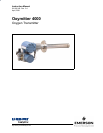

Instruction Manual
IB-106-340 Rev. 2.4
April, 2001
Rosemount Analytical Inc. A Division of Emerson Process Management iii
Oxymitter 4000
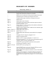
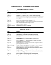
LIST OF ILLUSTRATIONS
Figure 1-1. Typical System Package ....................................................................................... 1-2
Figure 1-2. Oxymitter 4000 Autocalibration System Options.................................................. 1-3
Figure 1-3. Oxymitter 4000 HART Communications and AMS Application............................. 1-5
Figure 1-4. Typical System Installation .................................................................................... 1-6
Figure 1-5. SPS 4000............................................................................................................... 1-8
Figure 1-6. Model 751 Remote Powered Loop LCD Display.................................................. 1-9
Figure 2-1. Oxymitter 4000 Installation .................................................................................... 2-2
Figure 2-2. Oxymitter 4000 Installation (with SPS 4000) ......................................................... 2-3
Figure 2-3. Oxymitter 4000 with Abrasive Shield..................................................................... 2-4
Figure 2-4. Oxymitter 4000 Adapter Plate Dimensions............................................................ 2-5
Figure 2-5. Oxymitter 4000 Adapter Plate Installation ............................................................. 2-6
Figure 2-6. Oxymitter 4000 Bracing Installation....................................................................... 2-7
Figure 2-7. Orienting the Optional Vee Deflector..................................................................... 2-8
Figure 2-8. Installation with Drip Loop and Insulation Removal............................................... 2-8
Figure 2-9. Terminal Block .....................................................................................................2-10
Figure 2-10. SPS 4000 Electrical Connections........................................................................ 2-13
Figure 2-11. Air Set, Plant Air Connection ............................................................................... 2-14
Figure 2-12. Oxymitter 4000 Gas Connections Calibration Gas Connections......................... 2-15
Figure 3-1. Integral Electronics ................................................................................................ 3-1
Figure 3-2. Oxymitter 4000 Defaults ........................................................................................ 3-3
Figure 3-3. Startup and Normal Operation............................................................................... 3-5
Figure 3-4. Calibration Keys..................................................................................................... 3-6
Figure 4-1. Normal Operation...................................................................................................4-2
Figure 5-1. Signal Line Connections, ≥ 250 Ohms Lead Resistance ...................................... 5-2
Figure 5-2. Signal Line Connections, < 250 Ohms Lead Resistance ...................................... 5-2
Figure 5-3. Menu Tree for HART/AMS on the Oxymitter 4000................................................ 5-5
Figure 6-1. Oxymitter 4000 Exploded View.............................................................................. 6-2
Figure 6-2. Membrane Keypad................................................................................................. 6-3
Figure 6-3. Inside Right Cover .................................................................................................6-4
Figure 6-4. Terminal Block ....................................................................................................... 6-6
Figure 6-5. Electronic Assembly............................................................................................... 6-9
Figure 6-6. J8 Connector.......................................................................................................... 6-9
Figure 6-7. Fuse Location ......................................................................................................6-11
Figure 6-8. Heater Strut Assembly......................................................................................... 6-12
Figure 6-9. Cell Replacement Kit ........................................................................................... 6-13
Figure 6-10. Ceramic Diffusion Element Replacement............................................................ 6-15
Figure 6-11. SPS 4000 Manifold Assembly ............................................................................. 6-17
Figure 6-12. Power Supply Board and Interface Board Connections ...................................... 6-19
Figure 6-13. Calibration Gas and Reference Air Components ................................................ 6-23
Figure 7-1. Fault 1, Open Thermocouple................................................................................. 7-4
Figure 7-2. Fault 2, Shorted Thermocouple ............................................................................. 7-5
Figure 7-3. Fault 3, Reversed Thermocouple .......................................................................... 7-6
Figure 7-4. Fault 4, A/D Comm Error ....................................................................................... 7-7
Figure 7-5. Fault 5, Open Heater ............................................................................................. 7-8
Figure 7-6. Fault 6, High High Heater Temp............................................................................ 7-9
Figure 7-7. Fault 7, High Case Temp..................................................................................... 7-10
Figure 7-8. Fault 8, Low Heater Temp ................................................................................... 7-11
Figure 7-9. Fault 9, High Heater Temp .................................................................................. 7-12
Figure 7-10. Fault 10, High Cell mV......................................................................................... 7-13
Figure 7-11. Fault 11, Bad Cell ................................................................................................7-14