


Instruction Manual
IB-106-340 Rev. 2.4
April, 2001
Rosemount Analytical Inc. A Division of Emerson Process Management Troubleshooting 7-3
Oxymitter 4000
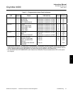
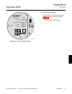
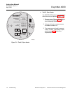
Table 7-1. Diagnostic/Unit Alarm Fault Definitions
LED Flashes Status 4-20 mA Line Fault
Self-
Clearing
HEATER T/C 1 OPEN Dependent on position 3 of SW2* 1 NO
2 SHORTED Dependent on position 3 of SW2* 2 NO
3 REVERSED Dependent on position 3 of SW2* 3 NO
4 A/D COMM ERROR Dependent on position 3 of SW2* 4 NO
HEATER 1 OPEN Dependent on position 3 of SW2* 5 NO
2 HIGH HIGH TEMP Dependent on position 3 of SW2* 6 NO
3 HIGH CASE TEMP Dependent on position 3 of SW2* 7 YES
4 LOW TEMP Dependent on position 3 of SW2* 8 YES
5 HIGH TEMP Dependent on position 3 of SW2* 9 YES
O2 CELL 1 HIGH mV Dependent on position 3 of SW2* 10 YES
3 BAD Track O
2
11 YES
4 EEPROM CORRUPT Dependent on position 3 of SW2* 12 NO
CALIBRATION 1 INVALID SLOPE Track O
2
13 YES
2 INVALID CONSTANT Track O
2
14 YES
3 LAST CALIBRATION
FAILED
Track O
2
15 YES
** CALIBRATION RECOM-
MENDED
Track O
2
YES
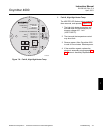
*Critical alarm conditions will render the O
2
measurement as unusable, and any of these events will cause the
4-20 mA signal to go to a user-selectable limit of 3.8 mA or 22 mA (position 3 of SW2). Factory default value is
3.8 mA. Alarms which are not “self-clearing” will require recycling of power to the electronics.
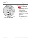
**The CALIBRATION RECOMMENDED alarm flashes the Calibration Recommended alarm LED on the opera-
tor’s keypad.
7