


Instruction Manual
IB-106-340 Rev. 2.4
April, 2001
2-8 Installation Rosemount Analytical Inc. A Division of Emerson Process Management
Oxymitter 4000
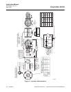
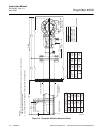
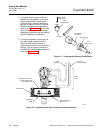
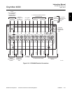
4. If using the optional ceramic diffusion
element, the vee deflector must be cor-
rectly oriented. Before inserting the
Oxymitter 4000, check the direction of
gas flow in the duct. Orient the vee de-
flector so the apex points upstream to-
ward the flow (Figure 2-7). This may be
done by loosening the setscrews and
rotating the vee deflector to the desired
position. Retighten the setscrews.
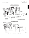
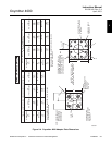
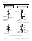
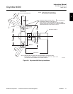
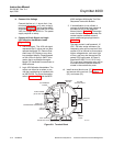
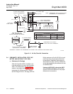
5. In vertical installations, ensure the sys-
tem cable drops vertically from the
Oxymitter 4000 and the conduit is
routed below the level of the electronics
housing. This drip loop minimizes the
possibility that moisture will damage the
electronics (Figure 2-8).
VEE
DEFLECTOR
VEE
DEFLECTOR
DIFFUSION
ELEMENT
SETSCREW
FILTER
GAS FLOW
DIRECTION
APEX
22220020
Figure 2-7. Orienting the Optional Vee Deflector
P
S
U
E
I
T
P
I
C
R
H
W
E
N
T
H
G
C
K
E
N
I
-
E
E
R
W
A
V
I
S
O
L
P
-
X
O
M
T
A
G
N
I
N
-
R
I
T
L
A
I
V
E
-
E
E
H
GAS
CAL.
DRIP
LOOP
LOGIC I/O,
4-20 mA SIGNAL
LINE
VOLTAGE
REPLACE INSULATION
AFTER INSTALLING
OXYMITTER 4000
INSULATION
ADAPTER
PLATE
STACK OR DUCT
METAL WALL
29340005
Figure 2-8. Installation with Drip Loop and Insulation Removal