


Instruction Manual
IB-106-340 Rev. 2.4
April, 2001
3-2 Startup Rosemount Analytical Inc. A Division of Emerson Process Management
Oxymitter 4000
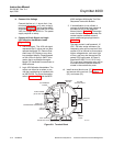
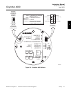
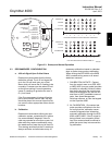
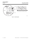
c. Verify Oxymitter 4000 Configuration
Located on the microprocessor board, the
top board, are two switches that configure
outputs for the Oxymitter 4000 (Figure 3-2).
SW1 determines if the 4-20 mA signal is
internally or externally powered. SW2 de-
termines:
1. Oxymitter 4000 status, HART or
LOCAL.
2. Oxygen range, 0 to 10% O
2
or 0 to
25% O
2
. (0 to 40% O
2
is also configur-
able only through HART/AMS.)
3. The 4-20 mA signal, at fault or power
up, 4 mA or 20 mA.
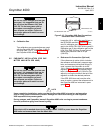
Remove power from the Oxymitter
4000 before changing defaults. If de-
faults are changed under power, dam-
age to the electronics package may
occur.
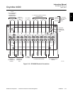
d. SW1
The two settings are internally or externally
powering the 4-20 mA signal. The factory
setting is for the 4-20 mA signal to be inter-
nally powered.
e. SW2
The factory sets this switch as follows:
1. Position 1 is HART/LOCAL. This switch
controls the configuration of the Oxy-
mitter 4000. The defaults cannot be
changed via HART/AMS unless the
switch is in the HART position. Placing
this switch in the LOCAL position
forces the O
2
range to the setting of
position 2. This switch must be placed
in the LOCAL position or changes in
position 2 will have no effect.
2. Position 2 determines the O
2
range.
This can be set to either 0 to 10% O
2
or 0 to 25% O
2
. The factory setting is 0
to 10% O
2
.
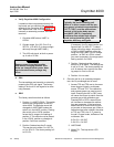
Typically, the probe’s sensing cell,
which is in direct contact with the pro-
cess gases, is heated to approximately
1357°F (736°C), and the external tem-
perature of the probe body may ex-
ceed 842°F (450°C). If operating
conditions also contain high oxygen
levels and combustible gases, the
Oxymitter 4000 may self-ignite.
If necessary, the O
2
range can be con-
figured from 0 to 40% O
2
. To select
values within this range, set position 1
of SW2 to HART and then enter the
range via HART/AMS. Do not change
position 1 of SW2 to LOCAL unless
you want to operate in the range speci-
fied by position 2 of SW2.
3. Position 3 determines the output at
startup or at an alarm. The settings are
4 mA or 20 mA. The factory setting is 4
mA. At startup, the current at the ana-
log output is 4 mA or 20 mA.
4. Position 4 is not used.
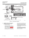
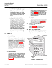
f. Once the cell is up to operating tempera-
ture, the O
2
percentage can be read:
1. Access TP5 and TP6 next to the mem-
brane keypad. Attach a multimeter
across TP5 and TP6. The calibration
and process gases can now be moni-
tored. Pressing the INC or DEC once
will cause the output to switch from the
process gas to the calibration gas.
Pressing INC or DEC a second time
will increase or decrease the calibra-
tion gas parameter. If the keys have
been inactive for one minute, the out-
put reverts to the process gas. When a
calibration has been initiated, the value
at TP5 and TP6 is the % O
2
seen by
the cell. Oxygen levels, as seen on the
multimeter, are:
8.0% O2 = 8.0 VDC
0.4% O2 = 0.4 VDC
2. HART/AMS.
3. Model 751. The loop-driven LCD
display.