


Instruction Manual
IB-106-340 Rev. 2.4
April, 2001
Rosemount Analytical Inc. A Division of Emerson Process Management Installation 2-9
Oxymitter 4000
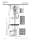
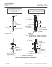
6. If the system has an abrasive shield,
check the dust seal gaskets. The joints
in the two gaskets must be staggered
180°. Also, make sure the gaskets are
in the hub grooves as the Oxymitter
4000 slides into the 15° forcing cone in
the abrasive shield.
NOTE
If process temperatures will exceed
392°F (200°C), use anti-seize com-
pound on stud threads to ease future
removal of Oxymitter 4000.
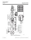
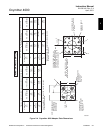
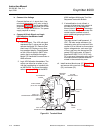
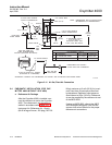
7. Insert probe through the opening in the
mounting flange and bolt the unit to the
flange. When probe lengths selected
are 9 or 12 ft (2.74 or 3.66 m), special
brackets are supplied to provide addi-
tional support for the probe inside the
flue or stack (Figure 2-6).
Uninsulated stacks or ducts may
cause ambient temperatures around
the electronics to exceed 149°F (65°C),
which may cause overheating damage
to the electronics.
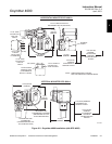
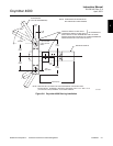
8. If insulation is being removed to access
the duct work for Oxymitter 4000
mounting, make sure the insulation is
replaced afterward (Figure 2-8).
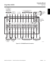
2-2 ELECTRICAL INSTALLATION (FOR
OXYMITTER 4000 WITHOUT SPS 4000)
All wiring must conform to local and national
codes.
Disconnect and lock out power before
connecting the unit to the power
supply.
Install all protective equipment covers
and safety ground leads after installa-
tion. Failure to install covers and
ground leads could result in serious
injury or death.
To meet the Safety Requirements of
IEC 1010 (EC requirement), and ensure
safe operation of this equipment, con-
nection to the main electrical power
supply must be made through a circuit
breaker (min 10 A) which will discon-
nect all current-carrying conductors
during a fault situation. This circuit
breaker should also include a me-
chanically operated isolating switch. If
not, then another external means of
disconnecting the supply from the
equipment should be located close by.
Circuit breakers or switches must
comply with a recognized standard
such as IEC 947.
NOTE
To maintain CE compliance, ensure a
good connection exists between the
mounting flange bolts and earth.
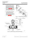
a. Remove screw (32, Figure 6-1), gasket (33),
and cover lock (34). Remove terminal block
cover (27).
2