


Instruction Manual
IB-106-340 Rev. 2.4
April, 2001
6-14 Maintenance and Service Rosemount Analytical Inc. A Division of Emerson Process Management
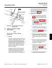
Oxymitter 4000
NOTE
To determine if the diffusion element
needs to be replaced, refer to para-
graph 6-2.
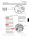
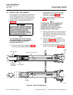
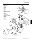
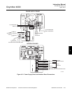
c. If equipped with the optional ceramic diffu-
sion assembly, remove and discard the
setscrews and remove the vee deflector
(Figure 6-10). Use spanner wrenches from
the probe disassembly kit (Table 9-1), to
turn the hub free from the retainer. Inspect
the diffusion element. If damaged, replace
the element.
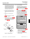
d. Loosen the four socket head cap screws
from the cell and flange assembly and re-
move the assembly and the corrugated
seal. The cell flange has a notch that may
be used to gently pry the flange away from
the probe. Note that the contact pad inside
of the probe will sometimes fuse to the oxy-
gen sensing cell. If the cell is fused to the
contact pad, push the cell assembly back
into the probe (against spring pressure) and
quickly twist the cell assembly. The cell and
contact pad should separate. If the contact
pad stays fused to the cell, a new
contact/thermocouple assembly must be in-
stalled. Disconnect the cell and the thermo-
couple wires at the probe electronics and
withdraw the cell with the wires still
attached.
e. Remove entire electronics per paragraph
6-5a, steps 2 through 6.
f. If the contact assembly is damaged, replace
the strut or the contact pad. Instructions for
replacing the contact pad are in the cell re-
placement kit.
g. Remove and discard the corrugated seal.
Clean the mating faces of the probe tube
and retainer. Remove burrs and raised
surfaces with a block of wood and crocus
cloth. Clean the threads on the retainer and
hub.
h. Rub a small amount of anti-seize compound
on both sides of the new corrugated seal.
i. Assemble the cell and flange assembly, cor-
rugated seal, and probe tube. Make sure
the calibration tube lines up with the cali-
bration gas passage in each component.
Apply a small amount of anti-seize com-
pound to the screw threads and use the
screws to secure assembly. Torque to 35 in-
lbs (4 N·m).
j. Install the entire electronics per paragraph
6-5a, steps 7 through 13.
k. Apply anti-seize compound to the threads of
the cell assembly, hub, and setscrews. Re-
install the hub on the cell assembly. Using
pin spanner wrenches, torque to 10 ft-lbs
(14 N·m). If applicable, reinstall the vee de-
flector, orienting apex toward gas flow. Se-
cure with the setscrews and anti-seize
compound. Torque to 25 in-lbs (2.8 N·m).
l. On systems equipped with an abrasive
shield, install the dust seal gaskets, with
joints 180° apart.
m. Reinstall the probe and gasket on the stack
flange.
n. Follow the instructions in paragraph 6-4a.2
to install the Oxymitter 4000 into the stack
or duct. If installing an Oxymitter 4000/SPS
4000 assembly, follow the instructions in
paragraph 6-4b.2. If there is an abrasive
shield in the stack, make sure the dust seal
gaskets are in place as they enter the 15°
reducing cone.
o. Turn on power and monitor thermocouple
output. It should stabilize at 29.3+0.2 mV.
Set reference air flow at 2 scfh (56.6 l/hr).
After the Oxymitter 4000 stabilizes, calibrate
the unit. If new components have been in-
stalled, repeat calibration after 24 hours of
operation.