


Instruction Manual
IB-106-340 Rev. 2.4
April, 2001
3-6 Startup Rosemount Analytical Inc. A Division of Emerson Process Management
Oxymitter 4000
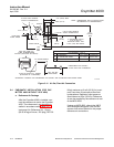
3. CALIBRATION FAILED. One contact
per probe from an SPS 4000 or IMPS
4000 to the control room for notification
that the calibration procedure failed.
Grouped with this alarm is an output
from a pressure switch which indicates
when the calibration gas bottles are
empty.
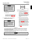
4. 4-20 mA SIGNAL DURING CALI-
BRATION. The 4-20 mA signal can be
configured to respond normally during
any calibration, or can be configured to
hold the last O
2
value upon the initiation
of calibration. Factory default is for the
4-20 mA signal to operate normally
throughout calibration. Holding the last
O
2
value may be useful if several
probes are being averaged for the pur-
pose of automatic control. Unless sev-
eral probes are being averaged, always
place any control loops using the O
2
signal into manual prior to calibrating.
3-4 POWER UP
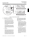
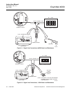
a. Startup Display
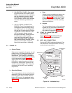
When power is applied to the probe, the cell
heater turns on. It takes approximately one
half hour for the cell to heat to operating
temperature. This condition is indicated by
the top four LEDs (DIAGNOSTIC ALARMS)
on the membrane keypad (Figure 3-3).
Starting with the CALIBRATION LED, the
LEDs light in ascending order until all four
LEDs are on. At this point, all four turn off
and the cycle starts again. This ramp cycle
continues until the cell is up to operating
temperature.
b. Operating Display
The ramp cycle turns into a cycle where the
diagnostic LEDs light in sequence from the
top to the bottom, one at a time. After the
bottom LED turns on, the sequence starts
again at the top with the HEATER T/C LED
(Figure 3-3).
c. Error
If there is an error condition at startup, one
of the diagnostics LEDs will be blinking.
Refer to Section 7, TROUBLESHOOTING,
to determine the cause of the error. Clear
the error, cycle power, and the operating
display should return.
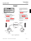
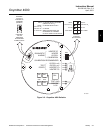
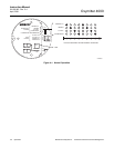
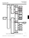
d. Keypad
The five membrane keys on the membrane
keypad are only used during calibration to
adjust the high and low gas and to initiate
the calibration sequence (Figure 3-4).
3-5 START UP OXYMITTER 4000
CALIBRATION
Refer to Section 6, MAINTENANCE AND
SERVICE, for calibration instructions.
3-6 IMPS 4000 CONNECTIONS
See the IMPS 4000 Intelligent Multiprobe Test
Gas Sequencer Instruction Bulletin for wiring
and pneumatic connections.
DIAGNOSTIC
ALARMS
TEST
POINTS
HEATERT/C
HEATER
02 CELL
CALIBRATION
CALIBRATION RECOMMENDED
02 CELL mV +
02 CELL mv -
HEATERT/C +
HEATERT/C -
INC INC
DEC DEC
HIGH
GAS
LOW
GAS
CAL
TEST GAS +
PROCESS -
% 02
MEMBRANE
KEYS
MEMBRANE
KEYS
MEMBRANE
KEY
DIAGNOSTIC
LEDS
22220023
Figure 3-4. Calibration Keys