


Instruction Manual
IB-106-340 Rev. 2.4
April, 2001
Rosemount Analytical Inc. A Division of Emerson Process Management Optional Accessories 11-1
Oxymitter 4000
SECTION 11
INDEX
This index is an alphabetized listing of parts, terms, and procedures having to do with the Haz-
ardous Area Oxygen/Combustibles Transmitter. Every item listed in this index refers to a location
in the manual by one or more page numbers.
A
Abrasive Shield, 2-1, 2-4, 2-9, 9-3, 9-4
Absolute Temperature, 1-1
Accuracy, 1-10
Adapter Plate, 1-2, 1-6, 2-1, 2-5, 2-6
Alarms, Diagnostic, 4-1, 6-6, 7-3
Alarms, Unit, 6-6, 7-3
AMS, 1-1, 1-4, 3-2, 5-1, 5-3, 6-3, 7-19, 10-1
Analog Output, 1-11, 2-10, 3-1, 5-2, 5-3
Arithmetic Constant, 1-1
Automatic Calibration, 6-1
B
Bracing, 2-7
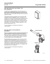
By-Pass Packages, 10-1
C
Calibration, 5-8, 6-1, 6-3, 7-1, 7-17, 7-18, 7-19
Calibration Gas, 1-5, 1-6, 1-7, 1-8, 1-10, 2-2, 2-3, 2-
4, 2-15, 6-1, 6-4, 6-5, 6-7, 6-8, 7-19, 7-20, 7-21, 7-
22, 10-3
Calibration Gas Bottles, 1-13, 9-7
Calibration Gas Flowmeter, 2-3
Calibration Interval, Timed, 5-9, 6-3
CALIBRATION RECOMMENDED, 1-3, 1-9, 3-4, 4-1,
6-3, 6-4, 6-5, 10-2
Cell, 1-4, 3-2, 6-13, 7-13, 7-14, 7-18
Cell Constant, 1-1
Cell Replacement Kit, 9-2, 9-3
Check Valve, 1-5, 6-20, 6-23, 7-20, 7-22
D
Diffusion Element, 1-4, 6-1, 6-13, 6-15, 6-21
Distributed Control System, 1-4
Drip Loop, 2-8
E
EEPROM, 7-15
Electronic Noise, 1-10, 7-1
Electronics, 1-2, 1-3, 1-4, 1-10, 6-8, 6-9, 6-10, 9-5,
9-6
Electronics Temperature, 1-10
Electrostatic Discharge, 7-1
Equipment Return, 8-1
F
Fuse, 6-10
G
Grounding, 7-1
H
HART, 1-1, 1-2, 1-3, 1-4, 3-2, 3-3, 5-1, 5-3, 5-5, 5-6,
5-7, 5-8, 6-3, 7-19, 10-1
HART Communicator, 1-4, 5-1, 5-3, 5-8, 10-1
HART Menu Tree, 5-5, 5-6, 5-7
Heater, 7-3, 7-8, 7-9, 7-10, 7-11, 7-12
Heater Strut, 6-12, 9-3
Heater Thermocouple, 1-4, 7-3, 7-4, 7-5, 7-6
I
IMPS 4000, 1-2, 1-3, 1-4, 1-5, 1-6, 1-7, 1-14, 2-10,
3-4, 3-5, 3-6, 5-4, 6-3, 7-2, 10-2
Installation, Electrical, 2-9, 2-11
Installation, Mechanical, 2-1
Installation, Pneumatic, 2-14, 2-15
Instrument Air, 1-5, 1-6, 1-7, 2-14, 6-7, 6-8
Insulation, 2-9, 6-7, 6-8
Integrated Circuits, 7-1
K
Keypad, Membrane, 1-4, 2-1, 3-2, 3-6, 6-3
L
Lengths, Probe, 2-9
Line Voltage, 1-6, 1-10, 2-10, 6-6, 6-7, 6-8
Logic I/O, 1-6, 1-11, 2-10, 3-1, 3-4, 5-3, 5-4, 6-6, 6-
7, 6-19, 7-20, 7-21
M
Manual Calibration, 6-3
Membrane Keypad, 1-4, 2-1, 3-2, 3-6, 6-3
Mounting, 1-10
11