


Instruction Manual
IB-106-340 Rev. 2.4
April, 2001
Rosemount Analytical Inc. A Division of Emerson Process Management Description and Specifications 1-5
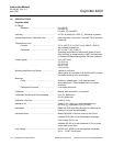
Oxymitter 4000
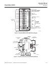
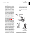
e. Handling the Oxymitter 4000
It is important that printed circuit
boards and integrated circuits are
handled only when adequate antistatic
precautions have been taken to pre-
vent possible equipment damage.
The Oxymitter 4000 is designed for in-
dustrial applications. Treat each com-
ponent of the system with care to
avoid physical damage. Some probe
components are made from ceramics,
which are susceptible to shock when
mishandled.
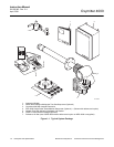
f. System Considerations
Prior to installing your Oxymitter 4000,
make sure you have all the components
necessary to make the system installation.
Ensure all the components are properly in-
tegrated to make the system functional.
After verifying that you have all the compo-
nents, select mounting locations and deter-
mine how each component will be placed in
terms of available line voltage, ambient
temperatures, environmental considera-
tions, convenience, and serviceability.
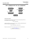
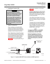
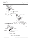
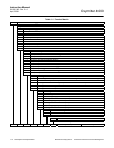
Figure 1-3 shows a typical system wiring. A
typical system installation is illustrated in
Figure 1-4.
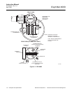
A source of instrument air is optional at the
Oxymitter 4000 for reference air use. Since
the unit is equipped with an in-place cali-
bration feature, provisions can be made to
permanently connect calibration gas tanks
to the Oxymitter 4000.
If the calibration gas bottles will be perma-
nently connected, a check valve is required
next to the calibration fittings on the integral
electronics.
This check valve is to prevent breathing of
the calibration gas line and subsequent flue
gas condensation and corrosion. The check
valve is in addition to the stop valve in the
calibration gas kit or the solenoid valves in
the IMPS 4000 or SPS 4000.
NOTE
The integral electronics is rated NEMA
4X (IP66) and is capable of operation
at temperatures up to 149°F (65°C).
Retain the packaging in which the
Oxymitter 4000 arrived from the fac-
tory in case any components are to be
shipped to another site. This packag-
ing has been designed to protect the
product.
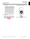
LINE VOLTAGE
2 CALIBRATION GAS LINES
BY CUSTOMER
[300 FT (90 M) MAX]
OXYMITTER 4000
WITH INTEGRAL ELECTRONICS
TERMINATION IN
CONTROL ROOM
ASSET MANAGEMENT SOLUTIONS
4-20 MA OUTPUT
(TWISTED PAIR)
HART MODEL 275
HAND HELD
INTERFACE
26170032
Figure 1-3. Oxymitter 4000 HART Communications and AMS Application
1