


Instruction Manual
IB-106-340 Rev. 2.4
April, 2001
Rosemount Analytical Inc. A Division of Emerson Process Management Installation 2-11
Oxymitter 4000
2-3 ELECTRICAL INSTALLATION (FOR OXY-
MITTER 4000 WITH SPS 4000)
All wiring must conform to local and national
codes.
Disconnect and lock out power before
connecting the unit to the power
supply.
Install all protective equipment covers
and safety ground leads after installa-
tion. Failure to install covers and
ground leads could result in serious
injury or death.
To meet the Safety Requirements of
IEC 1010 (EC requirement), and ensure
safe operation of this equipment, con-
nection to the main electrical power
supply must be made through a circuit
breaker (min 10 A) which will discon-
nect all current-carrying conductors
during a fault situation. This circuit
breaker should also include a me-
chanically operated isolating switch. If
not, then another external means of
disconnecting the supply from the
equipment should be located close by.
Circuit breakers or switches must
comply with a recognized standard
such as IEC 947.
Autocalibration systems will inject gases into the
probe and make electronic adjustments with no
operator attention required. The SPS 4000 pro-
vides solenoid valves and circuitry for calibrating
a single Oxymitter 4000 unit.
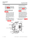
The SPS 4000 autocalibration system utilizes
the Oxymitter 4000’s bidirectional logic contact
as a “handshake” signal. Therefore, this signal
is not available for alarming purposes.
The following contacts are provided through the
autocalibration system:
a. One contact closure per probe from the
control room to the SPS 4000 for “calibra-
tion initiate”.
b. One contact output per probe from the SPS
4000 to the control room for “in calibration”
notification.
c. One contact per probe from the SPS 4000
to the control room for “calibration failed”
notification, which includes output from
pressure switch indicating “cal gas bottles
empty”.
NOTE
The 4-20 mA signal can be configured
to respond normally during any cali-
bration, or can be configured to hold
the last O
2
value upon the intitiation of
calibration. Factory default is for the
4-20 mA signal to operate normally
throughout calibration. Holding the
last O
2
value may be useful if several
probes are being averaged for the
purpose of automatic control. Unless
several probes are being averaged,
always place any control loops using
the O
2
signal into manual prior to
calibrating.
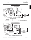
Electrically connect the probe as follows:
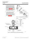
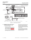
d. Remove screws (26, Figure 6-11) securing
terminal cover (27). Remove the cover to
expose terminal strip (25).
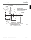
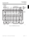
e. Connect Line Voltage
Route the line voltage leads into the mani-
fold through the 1/2 in. line voltage conduit
fitting (Figure 2-2) and out through the bot-
tom of the manifold. Connect the LINE IN
and NEUTRAL leads to terminals L and N,
respectively, as shown in Figure 2-10. Also,
be sure to connect the ground wire to the
ground lug. The unit automatically will con-
figure itself for 90 to 250 VAC line voltage
and 50/60 Hz. The power supply requires
no setup.
2