


Instruction Manual
IB-106-340 Rev. 2.4
April, 2001
Rosemount Analytical Inc. A Division of Emerson Process Management Maintenance and Service 6-5
Oxymitter 4000
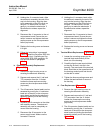
readings using the first cali-
bration gas and the CAL LED
will flash continuously. The
flashing indicates the Oxy-
mitter 4000 is ready to take
readings using the second
calibration gas.
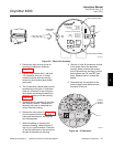
5 Remove the first calibration
gas and apply the second
calibration gas. (Electronics
will abort the calibration if step
6 is not done within 30
minutes).
6 Push the CAL key; the CAL
LED will be on solid. The
timer is activated for the sec-
ond calibration gas flow.
When the timer times out, the
CAL LED will flash a 2 pattern
flash or a 3 pattern flash (2
pattern flash equals a valid
calibration, 3 pattern flash
equals an invalid calibration).
If the slope or the constant is
out of specification, a diag-
nostic alarm LED will be
flashing. The diagnostic alarm
will remain active until the
purge cycle is over. If the
three pattern flash occurs
without a diagnostic alarm,
the calibration gases could be
the same or the calibration
gas was not turned on.
The CAL LED flashing indi-
cates the calibration is done.
(See Section 7, TROUBLE-
SHOOTING, for an explana-
tion of the 2 pattern and 3
pattern flashes).
7 Remove the second calibra-
tion gas and cap off the cali-
bration gas port.
8 Push the CAL key; the CAL
LED will be on solid as the
unit purges. (Default purge
time is three minutes). When
the purge is complete, the
CAL LED will turn off and the
Oxymitter 4000 output un-
locks from its held value and
begins to read the process O
2
.
If the calibration was valid, the DI-
AGNOSTIC ALARMS LEDs will in-
dicate normal operation. If the new
calibration values, slope or con-
stant, is not within the parameters,
the DIAGNOSTIC ALARMS LED
will indicate an alarm. (See Section
7, TROUBLESHOOTING, for
alarm codes). If the calibration was
invalid, the Oxymitter 4000 will re-
turn to normal operation, as it was
before a calibration was initiated,
and the parameters will not be
updated.
(e) Place control loop in automatic.
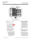
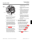
6-3 LED STATUS INDICATORS
a. Diagnostic/Unit Alarms
Table 6-1 lists the types and status of
alarms that will be encountered. (See
Section 7, TROUBLESHOOTING, for a de-
tailed description of each fault).
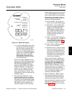
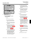
b. When the electronics determines a calibra-
tion is recommended, the CALIBRATION
RECOMMENDED LED is on solid.
c. The CAL LED turns on when a calibration is
recommended and is on during the calibra-
tion process. During calibration, the CAL
LED can be flashing, which would indicate
operator action is requested, or on solid,
which indicates calculations and measure-
ments are in progress.
6