


Instruction Manual
IB-106-340 Rev. 2.4
April, 2001
Rosemount Analytical Inc. A Division of Emerson Process Management Maintenance and Service 6-13
Oxymitter 4000
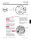
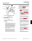
f. When replacing the strut, align the slot on
the heater plate with the calibration gas line
in the probe tube. Slide the strut into the
probe tube. It will turn to align the hole on
the back plate of the strut with the calibra-
tion gas line. When the hole and the cali-
bration gas line are aligned correctly, the
strut will slide in the rest of the way.
g. Push down on the back plate of the strut to
make sure you have spring tension and
then tighten the three screws on the back
plate.
h. Replace the CAL and REF gas silicon
tubes.
i. Install the entire electronics per paragraph
6-5a, steps 7 through 13.
j. Follow the instructions in paragraph 6-4a.2
to install the Oxymitter 4000 into the stack
or duct. If installing an Oxymitter 4000/SPS
4000 assembly, follow the instructions in
paragraph 6-4b.2.
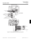
PROBETUBE
(NOT INCLUDED
IN KIT)
SOCKET HEAD
CAP SCREWS
CORRUGATED
SEAL
CELL AND
FLANGE
ASSEMBLY
CALIBRATION GAS
PASSAGE
22220028
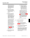
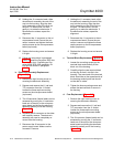
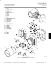
Figure 6-9. Cell Replacement Kit
6-8 CELL REPLACEMENT
This paragraph covers oxygen sensing cell re-
placement. Do not attempt to replace the cell
until all other possibilities for poor performance
have been considered. If cell replacement is
needed, order the cell replacement kit (Table
9-1).
The cell replacement kit (Figure 6-9) contains a
cell and flange assembly, corrugated seal,
setscrews, socket head cap screws, and anti-
seize compound. The items are carefully pack-
aged to preserve precise surface finishes. Do
not remove items from the packaging until they
are ready to be used. Spanner wrenches and
hex wrenches needed for this procedure are
part of an available special tools kit (Table 9-1).
Use heat-resistant gloves and clothing
when removing the probe. Do not at-
tempt to work on these components
until they have cooled to room tem-
perature. Probe components can be as
hot as 800°F (427°C). This can cause
severe burns.
Disconnect and lock out power before
working on any electrical components.
There is voltage of up to 115 VAC.
Do not remove the cell unless certain
it needs to be replaced. Removal may
damage the cell and platinum pad. Go
through the complete troubleshooting
procedure to make sure the cell needs
to be replaced before removing it.
a. Follow the instructions in paragraph 6-4a.1
to remove the Oxymitter 4000 from the
stack or duct. If removing an Oxymitter
4000/SPS 4000 assembly, follow the in-
structions in paragraph 6-4b.1.
b. If the probe uses the standard diffusion
element, use a spanner wrench to remove
the diffusion element.
6