


Instruction Manual
IB-106-340 Rev. 2.4
April, 2001
Rosemount Analytical Inc. A Division of Emerson Process Management Startup 3-1
Oxymitter 4000
SECTION 3
STARTUP
Install all protective equipment covers
and safety ground leads before
equipment startup. Failure to install
covers and ground leads could result
in serious injury or death.
3-1 GENERAL
a. Verify Mechanical Installation
Ensure the Oxymitter 4000 is installed cor-
rectly (Section 2, INSTALLATION).
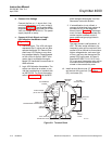
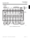
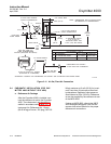
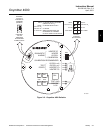
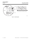
b. Verify Terminal Block Wiring
1. Remove screw (32, Figure 6-1), gasket
(33), and cover lock (34) that secure
the terminal block cover. Remove the
cover to expose the terminal block
(Figure 3-1).
2. Check the terminal block wiring. Be
sure the power, 4-20 mA signal, and
logic outputs are properly connected
and secure.
3. Install the housing cover on the termi-
nal block and secure with cover lock
(34, Figure 6-1), gasket (33), and
screw (32).
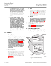
4. For an Oxymitter 4000 with an inte-
grally mounted SPS 4000, remove
screws (26, Figure 6-11) and terminal
cover (27). Check that the power and
signal terminations are properly con-
nected to terminal strip (25) and secure
according to instructions in Section 2,
INSTALLATION.
5. Install terminal cover (27) and secure
with screws (26).
AC L1
AC N
+
+
-
-
4-20
500 VA
SERIAL NO.
TAG NO.
OXYMITTER 4000
WATTS:VOLTS:
FUSE:LINE
OUTPUT:
Rosemount Analytical Inc.
Orrville, OH 44667-0901
85-264 VAC 48-62 Hz
TM
800-433-6076
4-20 mA
R
5 Amps
TM
HART
SMART FAMILY
DIAGNOSTIC
ALARMS
TEST
POINTS
HEATER T/C
HEATER
02 CELL
CALIBRATION
CALIBRATION RECOMMENDED
02 CELL mV +
02 CELL mv -
HEATER T/C +
HEATER T/C -
INC INC
DEC DEC
HIGH
GAS
LOW
GAS
CAL
TEST GAS +
PROCESS -
% 02
SW2
TP1
J1
TP2
TP3
R
ED
YEL
G
R
N
O
RG
TP4
TP5
TP6
O
N
4-20 mA
SIGNAL
LOGIC I/O
GROUND LUGS
TERMINAL
BLOCK
OXYMITTER 4000
ELECTRONICS
HOUSING
26170036
Figure 3-1. Integral Electronics
3