


Instruction Manual
IB-106-340 Rev. 2.4
April, 2001
2-12 Installation Rosemount Analytical Inc. A Division of Emerson Process Management
Oxymitter 4000
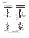
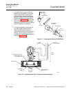
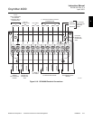
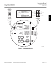
f. Connect Remote Contact Input Wiring
To set up the SPS 4000 to initiate a calibra-
tion from a remote location, route the 5 VDC
calibration initiate contact input leads
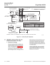
through the 1/2 in. NPT signal conduit port
(Figure 2-2) and out through the bottom of
the manifold. Connect the (+) and (-) CAL
INITIATE leads to terminals 1 and 2, re-
spectively, as shown in Figure 2-10.
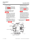
g. Connect Relay Output Wiring
Relay connections are available to signal
when the Oxymitter 4000 is in calibration or
when calibration failed. Relay outputs can
be connected to either indicator lights or a
computer interface. The relay contacts are
capable of handling a 5 to 30 VDC maxi-
mum power source.
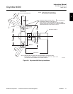
The cabling requirement is 1000 ft (303 m)
maximum. Route the relay output leads
through the 1/2 in. NPT signal conduit port
(Figure 2-2) and out through the bottom of
the manifold. Connect the (+) and (-) CAL
FAIL leads and the (+) and (-) IN CAL leads
to terminals 7, 8, 9, and 10, respectively, as
shown in Figure 2-10.
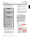
h. Connect 4-20 mA Signal Wiring
Route the 4-20 mA signal wiring into the
manifold through the 1/2 in. NPT signal
conduit port (Figure 2-2) and out through
the bottom of the manifold. Connect the (+)
and (-) signal leads to terminals 3 and 4, re-
spectively, as shown in Figure 2-10.
i. Once all connections are made, install ter-
minal cover (27, Figure 6-11) and secure
with screws (26).