


Instruction Manual
IB-106-340 Rev. 2.4
April, 2001
Rosemount Analytical Inc. A Division of Emerson Process Management Maintenance and Service 6-21
Oxymitter 4000
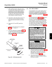
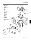
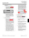
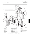
f. Pressure Regulator (Optional)
Maintenance
1. Pressure Adjustments. Reference air
pressure regulator (8, Figure 6-13) is
factory set to 20 psi (138 kPa). Adjust
using the knob on top of the pressure
regulator if necessary.
Do not use fingers to release valve
stem. The valve may release air at high
pressures and cause injury.
2. Condensation Drain. To drain excess
moisture from the filter bowl of refer-
ence air pressure regulator (8), use a
screwdriver or comparable tool to peri-
odically release valve stem on the bot-
tom of the regulator.
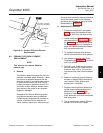
g. Flowmeter Adjustments
1. Calibration Gas Flowmeter. Calibration
gas flowmeter (17, Figure 6-13) regu-
lates the calibration gas flow and must
be set to 5 scfh. However, only adjust
the flowmeter to 5 scfh after placing a
new diffusion element on the end of the
Oxymitter 4000. Adjusting the flowme-
ter at any other time can pressurize the
cell and bias the calibration.
In applications with a heavy dust load-
ing, the O
2
probe diffusion element
may become plugged over time, caus-
ing a slower speed of response. The
best way to detect a plugged diffusion
element is to note the time it takes the
Oxymitter 4000 to return to the normal
process reading after the last calibra-
tion gas is removed and the calibration
gas line is blocked off. A plugged ele-
ment also can be indicated by a slightly
lower reading on the flowmeter.
Change the diffusion element when the
calibration gas flowmeter reads slightly
lower during calibration or when the re-
sponse time to the process flue gases
becomes very slow. Each time the diffu-
sion element is changed, reset the cali-
bration gas flowmeter to 5 scfh and
calibrate the Oxymitter 4000. For more
information on changing the diffusion
element, refer to paragraph 6-8.
2. Reference Air Flowmeter (Optional).
Reference air flowmeter (16, Figure
6-13) regulates the reference air and
must be set to 2 scfh. Adjust the flow
with the knob on the bottom of the ref-
erence air flowmeter when necessary.
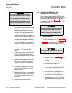
h. Flowmeter Replacement
Use this procedure to replace either refer-
ence air flowmeter (16, Figure 6-13) or cali-
bration gas flowmeter (17).
1. Turn off power to the system.
2. Shut off the calibration gases at the
cylinders.
3. Loosen, but do not remove, four
screws (13) securing flowmeter bracket
(25) to the manifold.
4. Flex the bottom of flowmeter bracket
(25) downward and away to disengage
and remove from the manifold.
5. For reference air flowmeter (16), re-
move pressure regulator (8) by discon-
necting tubing (11) from elbow fitting
(10). Also, disconnect tubing (24) from
straight fitting (23).
For calibration gas flowmeter (17), dis-
connect tubing (18) at elbow fitting
(21). Also, disconnect gas tubing (2)
from elbow fitting (15).
6