


Instruction Manual
IB-106-340 Rev. 2.4
April, 2001
6-8 Maintenance and Service Rosemount Analytical Inc. A Division of Emerson Process Management
Oxymitter 4000
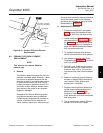
b. Oxymitter 4000 (with Integrally Mounted
SPS 4000)
1. Remove.
(a) Turn off power to the system.
(b) Shut off the calibration gases at
the cylinders and the instrument
air.
(c) Disconnect the instrument air and
calibration gas lines from the SPS
4000. If the instrument air does not
flow through the SPS 4000, dis-
connect the instrument air directly
at the Oxymitter 4000.
(d) Remove the screws securing the
terminal cover to the SPS 4000
manifold. Remove the terminal
cover to expose the terminal strip.
(e) Tag all customer-wired leads that
are connected to the terminal strip
before removing.
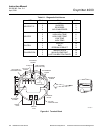
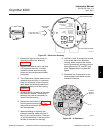
(f) On the terminal strip, loosen the
screws securing the customer-
wired LINE IN and NEUTRAL
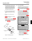
leads to terminals L and N (Figure
2-10). Also, remove the customer-
wired ground lead from the ground
lug. Remove the leads from the
terminal strip and slide them from
the manifold through the line volt-
age conduit port.
(g) Next, loosen the screws of remote
contact input terminals 1 and 2; 4-
20 mA terminals 3 and 4; and relay
output terminals 7, 8, 9, and 10.
Remove the leads from the termi-
nal strip and slide them from the
manifold through the signal conduit
port.
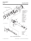
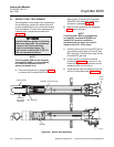
(h) Remove insulation to access the
mounting bolts. Unbolt the Oxy-
mitter 4000/SPS 4000 assembly
from the stack and take the entire
assembly to a clean work area.
(i) Allow the unit to cool to a comfort-
able working temperature.
2. Replace.
(a) Bolt the Oxymitter 4000/SPS 4000
assembly to the stack and install
insulation.
(b) Follow the instructions in para-
graph 2-3 to connect the line volt-
age and signal leads to an Oxy-
mitter 4000/ SPS 4000 assembly.
(c) Follow the instructions in para-
graph 2-5 to connect the calibra-
tion gases and instrument air to an
Oxymitter 4000/SPS 4000 assem-
bly. Turn on the calibration gases
at the cylinders and turn on instru-
ment air.
(d) Restore power to the system.
6-5 ELECTRONICS REPLACEMENT
Each of the following procedures details how to
remove and replace a specific electronic com-
ponent of the Oxymitter 4000.
NOTE
Recalibration is required whenever
electronic cards or sensing cell is re-
placed.
a. Entire Electronics Replacement
(with Housing)
NOTE
Only perform this procedure on Oxy-
mitter 4000 units without integrally
mounted SPS 4000 units. If it is neces-
sary to replace the entire electronics
on an Oxymitter 4000/ SPS 4000 as-
sembly, contact Rosemount for further
instructions.
1. Follow the instructions in paragraph
6-4a.1 to remove the Oxymitter 4000
from the stack or duct. If removing an
Oxymitter 4000/SPS 4000 assembly,
follow the instructions in paragraph
6-4b.1.