


Instruction Manual
IB-106-340 Rev. 2.4
April, 2001
7-2 Troubleshooting Rosemount Analytical Inc. A Division of Emerson Process Management
Oxymitter 4000
The logic contact is self-powered, +5 VDC,
340 ohm series resistance. An interposing
relay will be required if this contact is to be
utilized to annunciate a higher voltage de-
vice, such as a light or horn, and may also
be required for certain DCS input cards. A
Potter & Brumfield R10S-E1Y1-J1.0K 3.2
mA DC or an equal interposing relay will be
mounted where the contact wires terminate
in the control/relay room.
b. If autocalibration systems are utilized, the
bidirectional logic contact is utilized as a
“handshake” signal between the autocali-
bration system (SPS 4000 or IMPS 4000)
and is unavailable for alarming purposes.
The following additional contacts are pro-
vided through the autocalibration systems:
1. SPS 4000 and IMPS 4000, 1-4 probes.
(a) One contact closure per probe
from the control room to the SPS
4000 or IMPS 4000 for “calibration
initiate”.
(b) One contact output per probe from
the SPS 4000 or IMPS 4000 to the
control room for “in calibration”
notification.
(c) Once contact output per probe
from the SPS 4000 or IMPS 4000
to the control room for “calibration
failed” notification. (Includes output
from pressure switch indicating “cal
gas bottles empty”).
2. Additional IMPS 4000 Alarm Contacts.
(a) One contact per IMPS 4000 for
“low calibration gas flowing”.
(b) One contact per IMPS 4000 for
“high calibration gas flowing”.
NOTE
The 4-20 mA signal can be configured
to respond normally during any cali-
bration, or can be configured to hold
the last O
2
value upon the initiation of
calibration. Factory default is for the
4-20 mA signal to operate normally
throughout calibration. Holding the
last O
2
value may be useful if several
probes are being averaged for the
purpose of automatic control. Unless
several probes are being averaged,
always place any control loops using
the O
2
signal into manual prior to
calibrating.
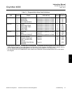
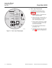
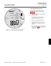
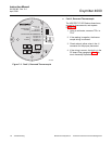
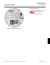
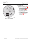
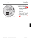
7-4 IDENTIFYING AND CORRECTING ALARM
INDICATIONS
Faults in the Oxymitter 4000 are indicated using
the four diagnostic, or unit, alarms. The pattern
of repeating blinks will define the problem. A
condensed table of the errors and the corre-
sponding blink codes can be found on the inside
right cover of the electronics housing. Table 7-1
also identifies the blink code and fault status of
each LED as well as the output of the 4-20 mA
signal line and a fault number that corresponds
to the troubleshooting instructions provided in
this section.