


Instruction Manual
IB-106-340 Rev. 2.4
April, 2001
Rosemount Analytical Inc. A Division of Emerson Process Management Maintenance and Service 6-9
Oxymitter 4000
500 VA
R
SERIAL NO.
TAG NO.
OXYMITTER 4000
VOLTS: WATTS:
OUTPUT: LINE FUSE:
Rosemount Analytical Inc.
Orrville,OH 44667-0901
85-264 VAC 48-62 Hz
TM
800-433-6076
4-20 mA
R
5 Amps
TM
HART
SMART FAMILY
DIAGNOSTIC
ALARMS
TEST
POINTS
HEATER T/C
HEATER
O2 CELL
CALIBRATION
CALIBRATION RECOMMENDED
O2 CELL mV +
O2 CELL mv -
HEATER T/C +
HEATER T/C -
INC INC
DEC DEC
HIGH
GAS
LOW
GAS
CAL
TEST GAS +
PROCESS -
% O2
SW2
TP1
J1
TP2
TP3
RED
YEL
GRN
ORG
TP4
TP5
TP6
ON
J1
MOUNTING
SCREW
MOUNTING SCREW
MOUNTING SCREW
26170018
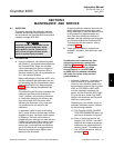
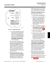
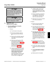
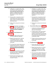
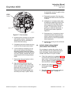
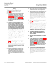
Figure 6-5. Electronic Assembly
2. Remove the right housing cover un-
covering the electronic assembly
(Figure 6-5).
3. Depress and remove the J1 (cell and
T/C) connector from the J1 socket.
Loosen the three captive mounting
screws on the microprocessor board
(top board).
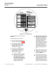
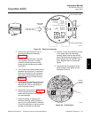
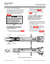
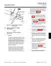
4. The J8 connector (heater leads) can be
accessed by moving the J1 connector
leads out of the slot on the microproc-
essor board and sliding the electronic
assembly partially out of the housing
(Figure 6-6).
5. Squeeze the J8 connector on the sides
and carefully remove. The electronic
assembly can now be completely re-
moved from the housing.
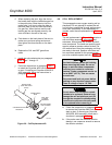
6. Remove the four screws (7, Figure 6-1)
from the probe finned housing. The
probe and the electronic housing can
now be separated.
7. When reinstalling or replacing the
electronic housing, make sure that O-
ring (10) is in good condition. Place the
J1 and J8 connectors in the hole on the
flat side of the electronic housing.
8. Hold the J1 and J8 connectors out and
to the probe side of the electronic
housing. Make sure that the conduit
port of the electronic housing is on the
same side as the CAL and REF gas
ports. Replace the four screws and
tighten.
9. Reconnect the J8 connector to the
power supply board. Make sure the
connector is secure.
3D39619G
REV
1
+
250VAC
TIME LAG
5A
+
+
+
+
+
+
+
+
1
J8
POWER
SUPPLY
BOARD
22220061
Figure 6-6. J8 Connector
6