


SECTION 24—ALARM TEST
Platinum™Series 94 Part No 1110538
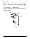
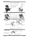
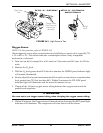
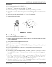
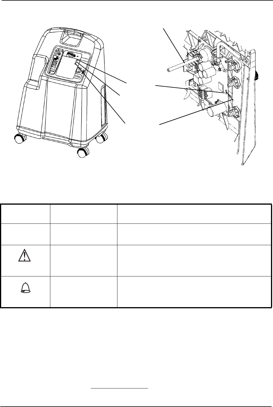
FIGURE 24.3 Oxygen Sensor
SENSO
2
ALARM THRESHOLD
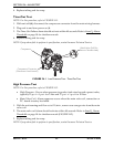
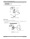
P.E. Valve Coil Test
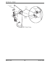
NOTE: For this procedure, refer to FIGURE 24.4.
NOTE: P.E. Valve Coil - Alarm sequence occurs when the P.E. Valve Coil, connection or P.C. Board
Circuitry has failed.
1. With the unit running and flow set at 5 L/min., remove one YELLOW wire from the
P.E. valve coil. The P.E. valve coil alarm should activate within 10 seconds.
2. Reinstall cabinet. Refer to Removing Cabinet on page 25.
NOTE: If any alarm fails to perform to specification, contact Invacare Technical Service.
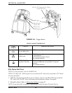
LABEL
SYMBOL
STATUS INDICATOR LIGHTS
SYSTEM OKAY
O
2
over 85% (± 2%)
GREEN Indicator Light
O
2
Between 73% (± 3%)
to 85% (±2%)
YELLOW Indicator light
A. YELLOW Solid
B. YELLOW Flashing Sensor Failure
Call a qualified technician.
SYSTEM FAILURE
O
2
Below 73% (±3%)
RED Indicator light
Continuous Audible Alarm Sieve-GARD™Compressor
Shutdown
Call a qualified technician
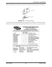
1/8-inch I.D. Oxygen Sensor Tubing
(Clamp Off Flow)
YELLOW light
(5LXO
2 and
10LXO
2 only)
RED light
GREEN light
O
2