SECTION 7—COMPRESSOR
Part No 1110538 49 Platinum™Series
CAUTION
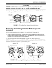
NEVER install the limiters on the bottom, or cylinder side, of the valve plate
assembly - doing so will result in unit not working or damaging the unit.
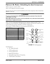
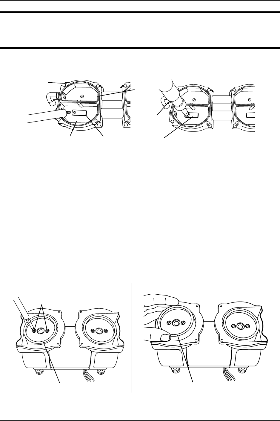
5. Center the exhaust valve and limiter over the port hole secure with .44 hex head screw
and torque to 10-13 inch-lbs.
FIGURE 7.17 Installing New Exhaust Valves And Limiters
Removing the Existing Retainer Plate, Cups and
Cylinders
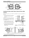
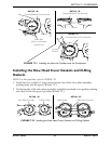
NOTE: For this procedure, refer to FIGURE 7.18 and FIGURE 7.19 on page 50.
1. Using a 1/8-inch Allen wrench, remove the two Allen head screws that secure the
retainer plate, cup and cylinder to the top of the compressor piston rod (Detail “A”).
Perform STEP 1 on both sides of the compressor.
2. Once the screws are removed, grasp the cylinder and lift up (Detail “B”).
NOTE: The cylinder, cup and retainer plate should all come off together. Refer to FIGURE 7.19 for
individual illustrations of cylinder, cup and retainer plate.
FIGURE 7.18 Removing the Existing Retainer Plate, Cups and Cylinders
Valve Plate
Assembly
Valve
Plate
Chamber
Exhaust Valve and Limiter
Torque
Wrench
.44 Hex Head Srew
DETAIL “A”
Allen Head Screws
Retainer Plate, Cup, and Cylinder
Retainer Plate, Cup, and Cylinder
DETAIL “B”


