


SECTION 7—COMPRESSOR
Platinum™Series 52 Part No 1110538
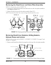
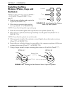
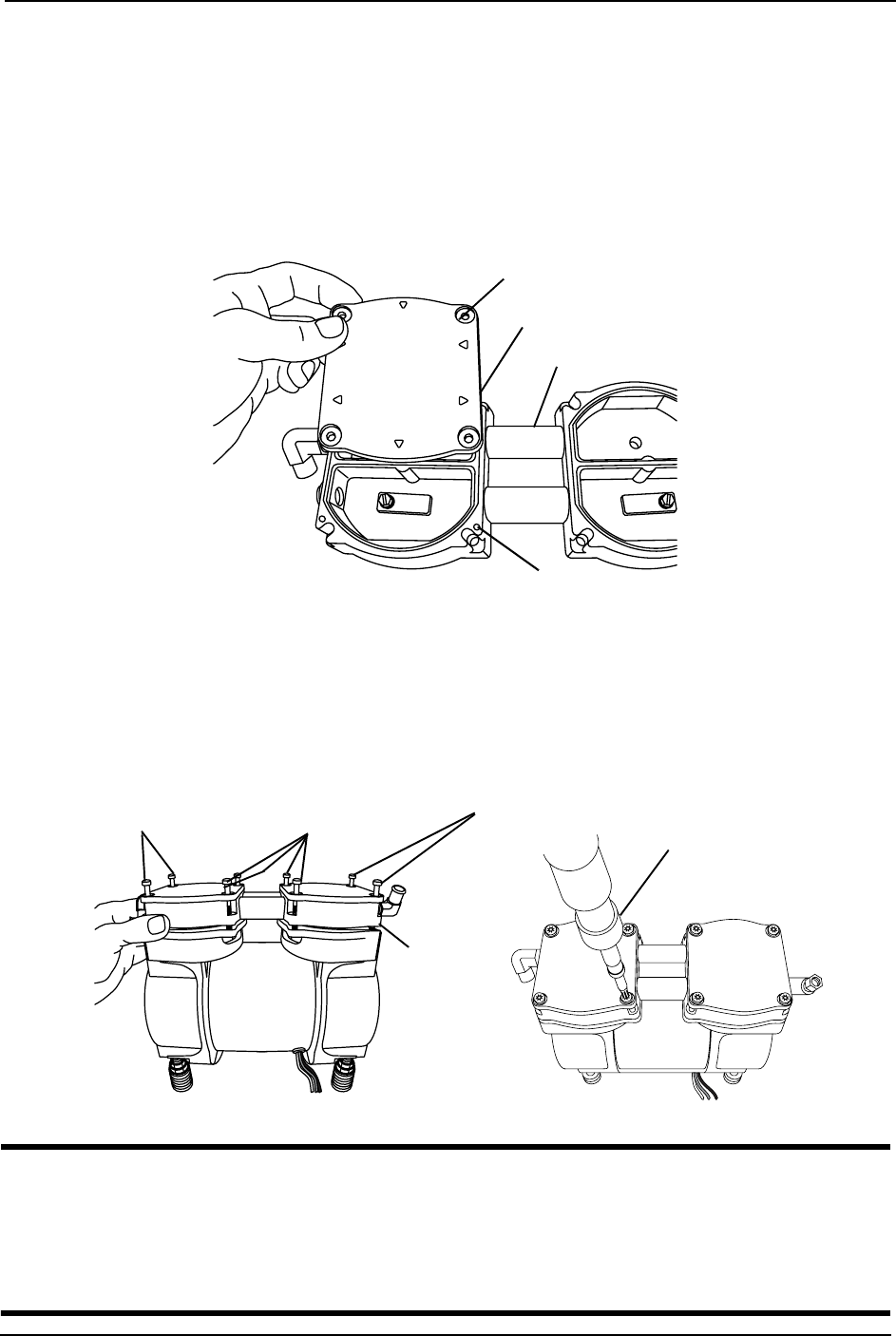
Installing the Head Cover
NOTE: For this procedure, refer to FIGURE 7.23 and FIGURE 7.24.
1. Install the head cover onto the valve plate assembly.
NOTE: When installing the head cover onto the valve plate assembly, ensure the alignment pins,
located on the underside of the head cover, engage into the alignment holes on the valve plate
assembly.
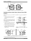
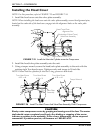
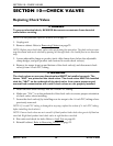
FIGURE 7.23 Install the New the Cylinder onto the Compressor
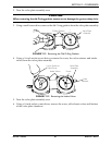
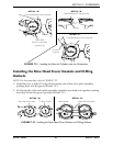
2. Install the head/valve plate assembly onto the unit.
3. Using a torque wrench, secure the head/valve plate assembly to the unit with the
existing eight Torx head screws. Tighten evenly and torque to 50 inch-lbs.
NOTE: Ensure that the cylinders fit into the O-ring grooves on both heads.
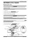
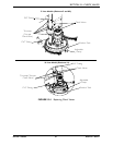
FIGURE 7.24 Install The Head Cover And Valve Plate Assembly Onto Compressor
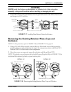
CAUTION
Slowly rotate compressor motor by grasping and turning one of the fans. The motor
shaft should rotate completely and freely. Any binding or stopping of the motor
indicates a problem in the assembly. If this occurs, disassemble, review steps and
reassemble. If problem persists, call Invacare at 1-800-832-4707.
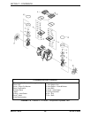
Valve Plate Assembly
Head Cover Plate
Alignment Pins
(Underside of Head Cover)
Alignment Pin Holes
Torx Head Screw
6-32 x .44
Torx Head Screw
6-32 x .44
Torx Head Screw
6-32 x .31
Valve Plate
Assembly
Torque Wrench