


SECTION 20—4-WAY VALVE
Part No 1110538 79 Platinum™Series
15. Replace the manifold assembly by performing the following:
A. Remove the four mounting screws that secure the 4-way valve to the existing
manifold assembly.
B. Separate the two components and discard existing manifold assembly.
C. Position existing 4-way valve onto new manifold assembly and loosely install
mounting screws through 4-way valve and into manifold assembly.
CAUTION
Torque sequence and specification MUST be adhered to or possible damage to the
4-way valve could result.
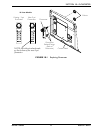
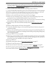
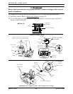
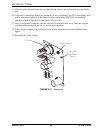
D. Pre-torque the mounting screws to 10 ± 2 inch-lbs using the torque sequence
(FIGURE 20.4).
E. The mounting screws can be now be torqued to 22 ± 2 inch-lbs in the same
sequence.
CAUTION
DO NOT attempt to perform any maintenance on the 4-way valve. This is a
maintenance-free valve. Opening the valve will void any and all warranties
applicable to the valve.
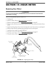
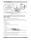
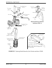
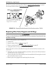
16. On the Y-tube assembly, check the muffler and replace if necessary. Refer to Replacing
the Exhaust Canister/Exhaust Muffler (Platinum 5 Models Manufactured before 7/24/
03) on page 29.
17. Install Y-tube muffler assembly onto bottom of manifold assembly.
18. Install one tie wrap on each leg of the Y-tube muffler assembly to secure in place.
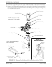
19. Install valve manifold input hose onto bottom center port of manifold assembly in the
orientation noted previously.
20. Secure valve manifold input hose with adjustable clamp.
21. Slide 4-way valve/manifold assembly complete through the cutout in top of sound box
then install the two mounting screws, washer and bushings into the manifold to
secure the 4-way valve assembly to the top of sound box.
22. Install valve manifold input hose onto end of heat exchanger and secure in place with
adjustable clamp.
23. Connect the two spade connectors to the valve pilot on top of the manifold assembly.
24. Connect sieve bed hoses to manifold assembly and secure in place with tie wrap.
25. Reinstall control panel. Refer to Removing Control Panel on page 62.
26. Plug unit in and turn power on ( ) .
27. Run unit and check for leaks at hose connections. Refer to Leak Test
on page 89.
I
/