SECTION 7—COMPRESSOR
Part No 1110538 43 Platinum™Series
Compressor
ƽ WARNING
To avoid personal injury or property damage, rotate the fan by hand prior to
connecting the unit to a power source. Check for suction at the air inlet by placing
your finger over the port as you rotate the fan. You should feel a slight suction with
each rotation of the fan. If you DO NOT feel a suction but you feel or hear a thump
as you turn the fan, DO NOT connect the unit to a power source. Review the
assembly procedure for possible error.
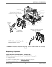
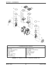
NOTE: For this procedure, refer to FIGURE 7.8 on page 44.
1. Reinstall compressor. Refer to Replacing Compressor Assembly on page 33.
2. Run unit and check for leaks around compressor hoses and compressor tubes. Refer
to Leak Test on page 89.
3. Take pressure readings to ensure proper system pressures. Refer to Installing the Sieve
Bed Pressure Tap-In Kit Installation and Checking Bed Pressure on page 96.
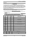
FIELD SERVICE PARTS LIST FOR THOMAS 2660 SERIES COMPRESSOR
2660CE37-989 COMPRESSOR
ITEM
NO.
PART
NO.
QTY.
PER ASM
QTY.
PER UNIT DESCRIPTION
1 See Chart — 2 Connecting Rod, Eccentric & Bearing Assembly
2 624277 1 2 Piston Cup
3 625776 1 2 Screw - Piston Cup Retainer
4 626175 1 2 Piston Cup Retainer
5 618114 1 2 Cylinder Sleeve
6 See Chart — 1 Head
7 623143 — 2 O-Ring - Head Gasket
8 625175 — 8 Screw - Head
9 621591 — 2 Valve Plate Assembly
638574 — 1 Valve - Pressure Relief-Not Shown (115 V)
10 617177 1 2 Valve Restraint
11 617562 2 4 Valve Keeper Strip
12 621485 2 4 Valve Flapper - Intake & Exhaust
13 621641 1 2 Valve Plate
14 625094 2 4 Screw - Valve Flapper
15 623137 — 2 O-Ring Valve Plate
16 638281 — 1 Fan - Gray
17 638282 — 1 Fan - Black
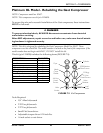
ITEM PART NO. QTY. DESCRIPTION
1 607731 2 Connecting Rod, Eccentric & Bearing Assembly
6 665167 1 Head


