8XC251SA, SB, SP, SQ USER’S MANUAL
2-8
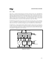
The watchdog timer is a circuit that automatically resets the 8XC251Sx in the event of a hardware
or software upset. When enabled by software, the watchdog timer begins running, and unless
software intervenes, the timer reaches a maximum count and initiates a chip reset. In normal op-
eration, software periodically clears the timer register to prevent the reset. If an upset occurs and
software fails to clear the timer, the resulting chip reset disables the timer and returns the system
to a known state. The watchdog and the timer/counters are described in Chapter 8, “Tim-
er/Counters and WatchDog Timer.”
2.3.2 Programmable Counter Array (PCA)
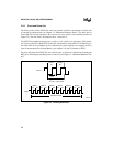
The programmable counter array (PCA) has its own timer and five capture/compare modules that
perform several functions: capturing (storing) the timer value in response to a transition on an in-
put pin; generating an interrupt request when the timer matches a stored value; toggling an output
pin when the timer matches a stored value; generating a programmable PWM (pulse width mod-
ulator) signal on an output pin; and serving as a software watchdog timer. Chapter 9, “Program-
mable Counter Array,” describes this peripheral in detail.
2.3.3 Serial I/O Port
The serial I/O port provides one synchronous and three asynchronous communication modes.
The synchronous mode (mode 0) is half-duplex: the serial port outputs a clock signal on one pin
and transmits or receives data on another pin.
The asynchronous modes (modes 1–3) are full-duplex (i.e., the port can send and receive simul-
taneously). Mode 1 uses a serial frame of 10 bits: a start bit, 8 data bits, and a stop bit. The baud
rate is generated by overflow of timer 1 or timer 2. Modes 2 and 3 use a serial frame of 11 bits: a
start bit, eight data bits, a programmable ninth data bit, and a stop bit. The ninth bit can be used
for parity checking or to specify that the frame contains an address and data. In mode 2, you can
use a baud rate of 1/32 or 1/64 of the oscillator frequency. In mode 3, you can use the overflow
from timer 1 or timer 2 to determine the baud rate.
In its synchronous modes (modes 1–3) the serial port can operate as a slave in an environment
where multiple slaves share a single serial line. It can accept a message intended for itself or a
message that is being broadcast to all of the slaves, and it can ignore a message sent to another
slave.


