8XC251SA, SB, SP, SQ USER’S MANUAL
9-8
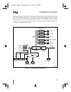
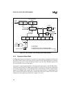
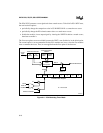
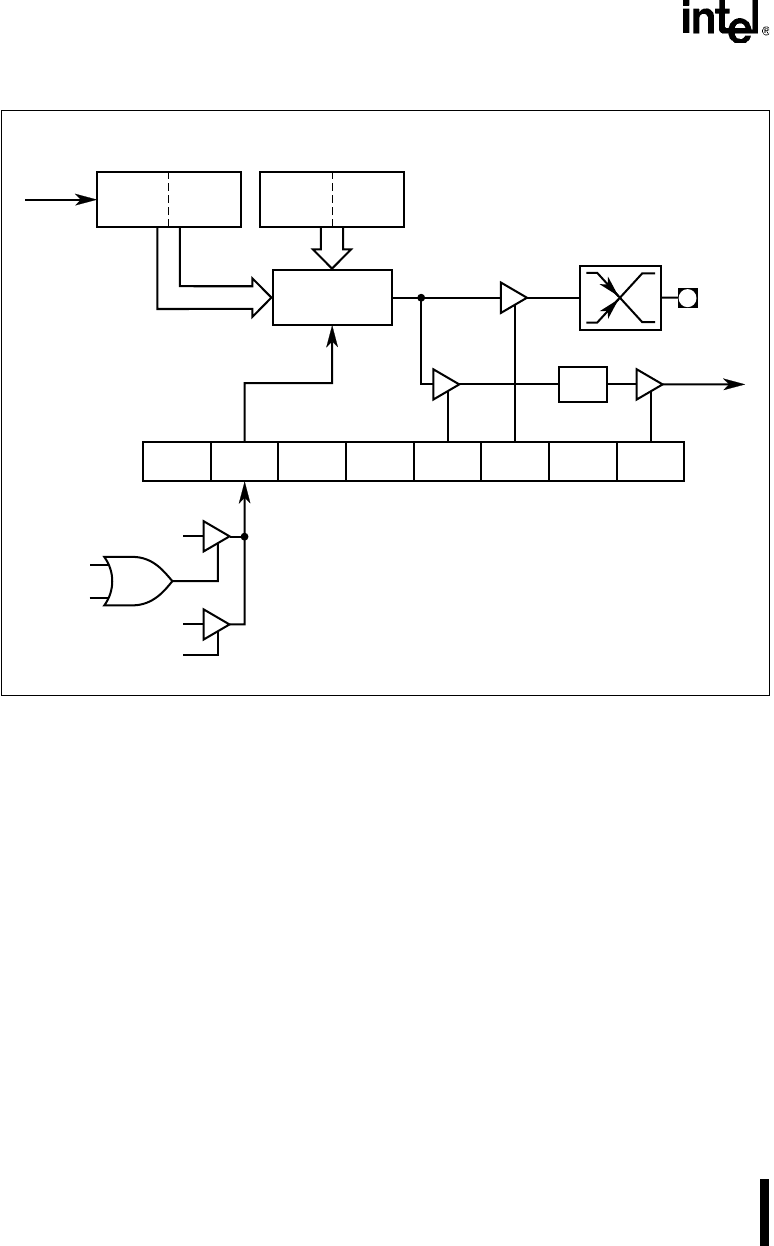
Figure 9-3. PCA Software Timer and High-speed Output Modes
9.3.4 High-speed Output Mode
The high-speed output mode (Figure 9-3) generates an output signal by toggling the module’s I/O
pin (CEXx) when a match occurs. This provides greater accuracy than toggling pins in software
because the toggle occurs before the interrupt request is serviced. Thus, interrupt response time
does not affect the accuracy of the output.
To program a compare/capture module for the high-speed output mode, set the ECOMx, MATx,
TOGx bits in the module’s CCAPMx register. Table 9-3 on page 9-14 lists the bit combinations
for selecting module modes. A match between the PCA timer/counter and the compare/capture
registers (CCAPxH/CCAPxL) toggles the CEXx pin and sets the module’s compare/capture flag
(CCFx in the CCON register). By setting or clearing the CEXx pin in software, the user selects
whether the match toggles the pin from low to high or vice versa.
A4164-01
CCAP
x
H
(8 Bits)
CCAP
x
L
(8 Bits)
CH
(8 Bits)
CL
(8 Bits)
CEX
x
X ECOM
x
0 0 TOG
x
0 ECCF
x
MAT
x
CCF
x
PCA Timer/Counter
Enable
Interrupt
Request
07
CCAPM
x
Mode Register
X = Don't Care
x
= 0, 1, 2, 3, 4
For software timer mode, set ECOM
x
and MAT
x
.
For high speed output mode, set ECOM
x
, MAT
x
, and TOG
x
.
Compare/Capture
Module
16-Bit
Comparator
Count
Input
Reset
Write to
CCAP
x
L
"0"
Match
"1"
Write to CCAP
x
H
Toggle
Enable
CCON


