A-1
APPENDIX A
INSTRUCTION SET REFERENCE
This appendix contains reference material for the instructions in the MCS
®
251 architecture. It
includes an opcode map, a summary of the instructions — with instruction lengths and execution
times — and a detailed description of each instruction. It contains the following tables:
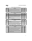
• Tables A-1 through A-4 describe the notation used for the instruction operands. Table A-5
describes the notation used for control instruction destinations.
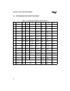
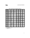
• Tables A-6 and A-7 comprise the opcode map for the instruction set.
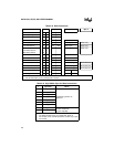
• Tables A-8 through A-17 contain supporting material for the opcode map.
• Table A-18 lists execution times for a group of instructions that access the port SFRs.
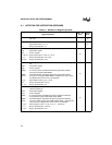
• The following tables list the instructions giving length (in bytes) and execution time:
Add and Subtract Instructions, Table A-19
Compare Instructions, Table A-20
Increment and Decrement Instructions, Table A-21
Multiply, Divide, and Decimal-adjust Instructions, Table A-22
Logical Instructions, Table A-23
Move Instructions, Table A-24
Exchange, Push, and Pop Instructions, Table A-25
Bit Instructions, Table A-26
Control Instructions, Table A-27
“Instruction Descriptions” on page A-26 contains a detailed description of each instruction.
NOTE
The instruction execution times given in this appendix are for code executing
from on-chip code memory and for data that is read from and written to on-
chip RAM. Execution times are increased by executing code from external
memory, accessing peripheral SFRs, accessing data in external memory, using
a wait state, or extending the ALE pulse.
For some instructions, accessing the port SFRs, Px, x = 0–3, increases the
execution time. These cases are listed in Table A-18 and are noted in the
instruction summary tables and the instruction descriptions.
i_opcode.fm5 Page 1 Thursday, June 27, 1996 1:41 PM


