8XC251SA, SB, SP, SQ USER’S MANUAL
A-22
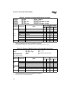
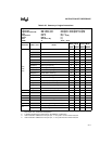
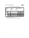
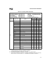
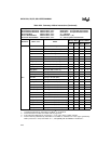
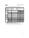
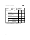
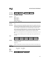
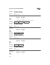
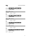
Table A-25. Summary of Exchange, Push, and Pop Instructions
Exchange Contents XCH <dest>,<src> A ↔ src opnd
Exchange Digit XCHD <dest>,<src> A3:0 ↔ on-chip RAM bits 3:0
Push PUSH <src> SP ← SP + 1; (SP) ← src
Pop POP <dest> dest ← (SP); SP ← SP – 1
Mnemonic <dest>,<src> Notes
Binary Mode Source Mode
Bytes States Bytes States
XCH
A,Rn Acc and reg 1 3 2 4
A,dir8 Acc and dir addr 2 3 (2) 2 3 (2)
A,@Ri Acc and on-chip RAM (8-bit addr) 1 4 2 5
XCHD
A,@Ri Acc and low nibble in on-chip RAM
(8-bit addr)
1425
PUSH
dir8 Push dir byte onto stack 2 2 2 2
#data Push immediate data onto stack 4 4 3 3
#data16 Push 16-bit immediate data onto
stack
5545
Rm Push byte reg onto stack 3 4 2 3
WRj Push word reg onto stack 3 6 2 5
DRk Push double word reg onto stack 3 10 2 9
POP
dir8 Pop dir byte from stack 2 3 2 3
Rm Pop byte reg from stack 3 3 2 2
WRj Pop word reg from stack 3 5 2 4
DRk Pop double word reg from stack 3 9 2 8
NOTES:
1. A shaded cell denotes an instruction in the MCS
®
51 architecture.
2. If this instruction addresses an I/O port (P
x
,
x
= 0–3), add 2 to the number of states.


