8-3
TIMER/COUNTERS AND WATCHDOG TIMER
For timer operation (C/Tx# = 0), the timer register counts the divided-down system clock. The
timer register is incremented once every peripheral cycle, i.e., once every six states (see section
2.2.2, “Clock and Reset Unit”). Since six states equals 12 clock cycles, the timer clock rate is
F
OSC
/12. Exceptions are the timer 2 baud rate and clock-out modes, where the timer register is
incremented by the system clock divided by two.
For counter operation (C/Tx# = 1), the timer register counts the negative transitions on the Tx ex-
ternal input pin. The external input is sampled during every S5P2 state. Section 2.2.2, “Clock and
Reset Unit,” describes the notation for the states in a peripheral cycle. When the sample is high
in one cycle and low in the next, the counter is incremented. The new count value appears in the
register during the next S3P1 state after the transition was detected. Since it takes 12 states (24
oscillator periods) to recognize a negative transition, the maximum count rate is 1/24 of the os-
cillator frequency. There are no restrictions on the duty cycle of the external input signal, but to
ensure that a given level is sampled at least once before it changes, it should be held for at least
one full peripheral cycle.
8.3 TIMER 0
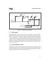
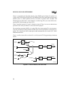
Timer 0 functions as either a timer or event counter in four modes of operation. Figures 8-2, 8-3,
and 8-4 show the logical configuration of each mode.
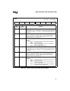
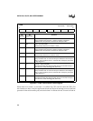
Timer 0 is controlled by the four low-order bits of the TMOD register (Figure 8-5) and bits 5, 4,
1, and 0 of the TCON register (Figure 8-6). The TMOD register selects the method of timer gating
(GATE0), timer or counter operation (T/C0#), and mode of operation (M10 and M00). The
TCON register provides timer 0 control functions: overflow flag (TF0), run control (TR0), inter-
rupt flag (IE0), and interrupt type control (IT0).
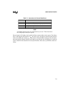
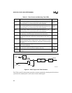
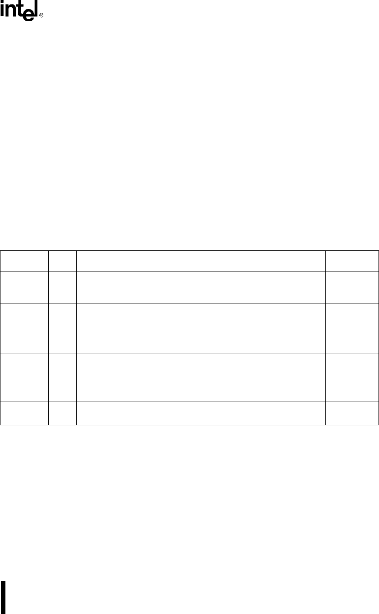
Table 8-2. External Signals
Signal
Name
Type Description
Alternate
Function
T2 I/O Timer 2 Clock Input/Output. This signal is the external clock input
for the timer 2 capture mode; and it is the timer 2 clock-output for the
clock-out mode.
P1.0
T2EX I Timer 2 External Input. In timer 2 capture mode, a falling edge
initiates a capture of the timer 2 registers. In auto-reload mode, a
falling edge causes the timer 2 registers to be reloaded. In the up-
down counter mode, this signal determines the count direction:
high = up, low = down.
P1.1
INT1:0# I External Interrupts 1:0. These inputs set the IE1:0 interrupt flags in
the TCON register. TCON bits IT1:0 select the triggering method:
IT1:0 = 1 selects edge-triggered (high-to-low);IT1:0 = 0 selects level-
triggered (active low). INT1:0# also serves as external run control for
timer 1:0 when selected by TCON bits GATE1:0#.
P3.3:2
T1:0 I Timer 1:0 External Clock Inputs. When timer 1:0 operates as a
counter, a falling edge on the T1:0 pin increments the count.
P3.5:4


