9-1
CHAPTER 9
PROGRAMMABLE COUNTER ARRAY
This chapter describes the programmable counter array (PCA), an on-chip peripheral of the
8XC251Sx that performs a variety of timing and counting operations, including pulse width mod-
ulation (PWM). The PCA provides the capability for a software watchdog timer (WDT).
9.1 PCA DESCRIPTION
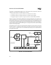
The programmable counter array (PCA) consists of a 16-bit timer/counter and five 16-bit com-
pare/capture modules. The timer/counter serves as a common time base and event counter for the
compare/capture modules, distributing the current count to the modules by means of a 16-bit bus.
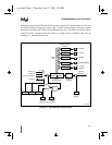
A special function register (SFR) pair, CH/CL, maintains the count in the timer/counter, while
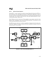
five SFR pairs, CCAPxH/CCAPxL, store values for the modules (see Figure 9-1). Additional
SFRs provide control and mode select functions as follows:
• The PCA timer/counter mode register (CMOD) and the PCA timer/counter control register
(CCON) control the operation of the timer/counter. See Figure 9-7 on page 9-13 and Figure
9-8 on page 9-14.
• Five PCA module mode registers (CCAPMx) specify the operating modes of the
compare/capture modules. See Figure 9-9.
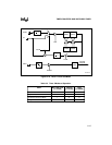
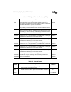
For a list of SFRs associated with the PCA, see Table 9-1. For an address map of all SFRs, see
Table 3-5 on page 3-17. Port 1 provides external I/O for the PCA on a shared basis with other
functions. Table 9-2 identifies the port pins associated with the timer/counter and compare/cap-
ture modules. When not used for PCA I/O, these pins can be used for standard I/O functions.
The operating modes of the five compare/capture modules determine the functions performed by
the PCA. Each module can be independently programmed to provide input capture, output com-
pare, or pulse width modulation. Module 4 only also has a watchdog-timer mode.
The PCA timer/counter and the five compare/capture modules share a single interrupt vector. The
EC bit in the IE special function register is a global interrupt enable for the PCA. Capture events,
compare events in some modes, and PCA timer/counter overflow all set flags in the CCON reg-
ister. Setting the overflow flag (CF) generates a PCA interrupt request if the PCA timer/counter
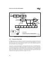
interrupt enable bit (ECF) in the CMOD register is set (Figure 9-1). Setting a compare/capture
flag (CCFx) generates a PCA interrupt request if the ECCFx interrupt enable bit in the corre-
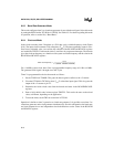
sponding CCAPMx register is set (Figures 9-2 and 9-3). For a description of the 8XC251Sx in-
terrupt system see Chapter 6, “Interrupt System.”


