


8XC251SA, SB, SP, SQ USER’S MANUAL
4-16
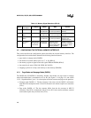
4.7 MAPPING ON-CHIP CODE MEMORY TO DATA MEMORY (EMAP#)
For devices with 16 Kbytes of on-chip code memory (87C251SB, SQ and 83C251SB, SQ), the
EMAP# bit (UCONFIG1.0) provides the option of accessing the upper half of on-chip code mem-
ory as data memory. This allows code constants to be accessed as data in region 00: using direct
addressing. See section 3.2.2.1, “Accessing On-chip Code Memory in Region 00:,” for the exact
conditions required for this mapping to be effective.
EMAP# = 0. For 87C251SB/83C251SB and 87C251SQ/83C251SQ, the upper 8 Kbytes of on-
chip code memory (FF:2000–FF:3FFFH) are mapped to locations 00:E000H–00:FFFFH.
EMAP# = 1. Mapping of on-chip code memory to region 00: does not occur. Addresses in the
range 00:E000H–00:FFFFH access external RAM.
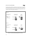
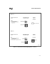
4.8 INTERRUPT MODE (INTR)
The INTR bit (UCONFIG1.4) determines what bytes are stored on the stack when an interrupt
occurs and how the RETI (Return from Interrupt) instruction restores operation.
For INTR = 0, an interrupt pushes the two lower bytes of the PC onto the stack in the following
order: PC.7:0, PC.15:8. The RETI instruction pops these two bytes in the reverse order and uses
them as the 16-bit return address in region FF:.
For INTR = 1, an interrupt pushes the three PC bytes and the PSW1 register onto the stack in the
following order: PSW1, PC.23:16, PC.7:0, PC.15:8. The RETI instruction pops these four bytes
and then returns to the specified 24-bit address, which can be anywhere in the 16-Mbyte address
space.