


10-11
SERIAL I/O PORT
10.6.3.1 Timer 1 Generated Baud Rates (Modes 1 and 3)
Timer 1 is the default baud rate generator for the transmitter and the receiver in modes 1 and 3.
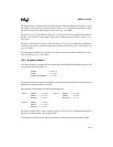
The baud rate is determined by the timer 1 overflow rate and the value of SMOD, as shown in the
following formula:
10.6.3.2 Selecting Timer 1 as the Baud Rate Generator
To select timer 1 as the baud rate generator:
• Disable the timer interrupt by clearing the ETI bit in the IE0 register (Figure 6-2 on page
6-6).
• Configure timer 1 as a timer or an event counter (set or clear the C/T# bit in the TMOD
register, Figure 8-5 on page 8-7).
• Select timer mode 0–3 by programming the M1, M0 bits in the TMOD register.
In most applications, timer 1 is configured as a timer in auto-reload mode (high nibble of TMOD
= 0010B). The resulting baud rate is defined by the following expression:
Timer 1 can generate very low baud rates with the following setup:
• Enable the timer 1 interrupt by setting the ET1 bit in the IE register.
• Configure timer 1 to run as a 16-bit timer (high nibble of TMOD = 0001B).
• Use the timer 1 interrupt to initiate a 16-bit software reload.
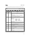
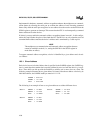
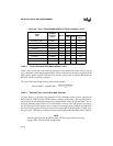
Table 10-4 lists commonly used baud rates and shows how they are generated by timer 1.
Serial I/O Modes 1 and 3 Baud Rate 2
SMOD1
Timer 1 Overflow Rate
32
------------------------------------------------------------
×=
Serial I/O Modes 1 and 3 Baud Rate 2
SMOD1
F
OSC
32 12 256 TH1)(–[]××
------------------------------------------------------------------
×=