


8XC251SA, SB, SP, SQ USER’S MANUAL
10-6
10.2.2 Asynchronous Modes (Modes 1, 2, and 3)
The serial port has three asynchronous modes of operation.
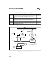
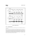
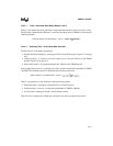
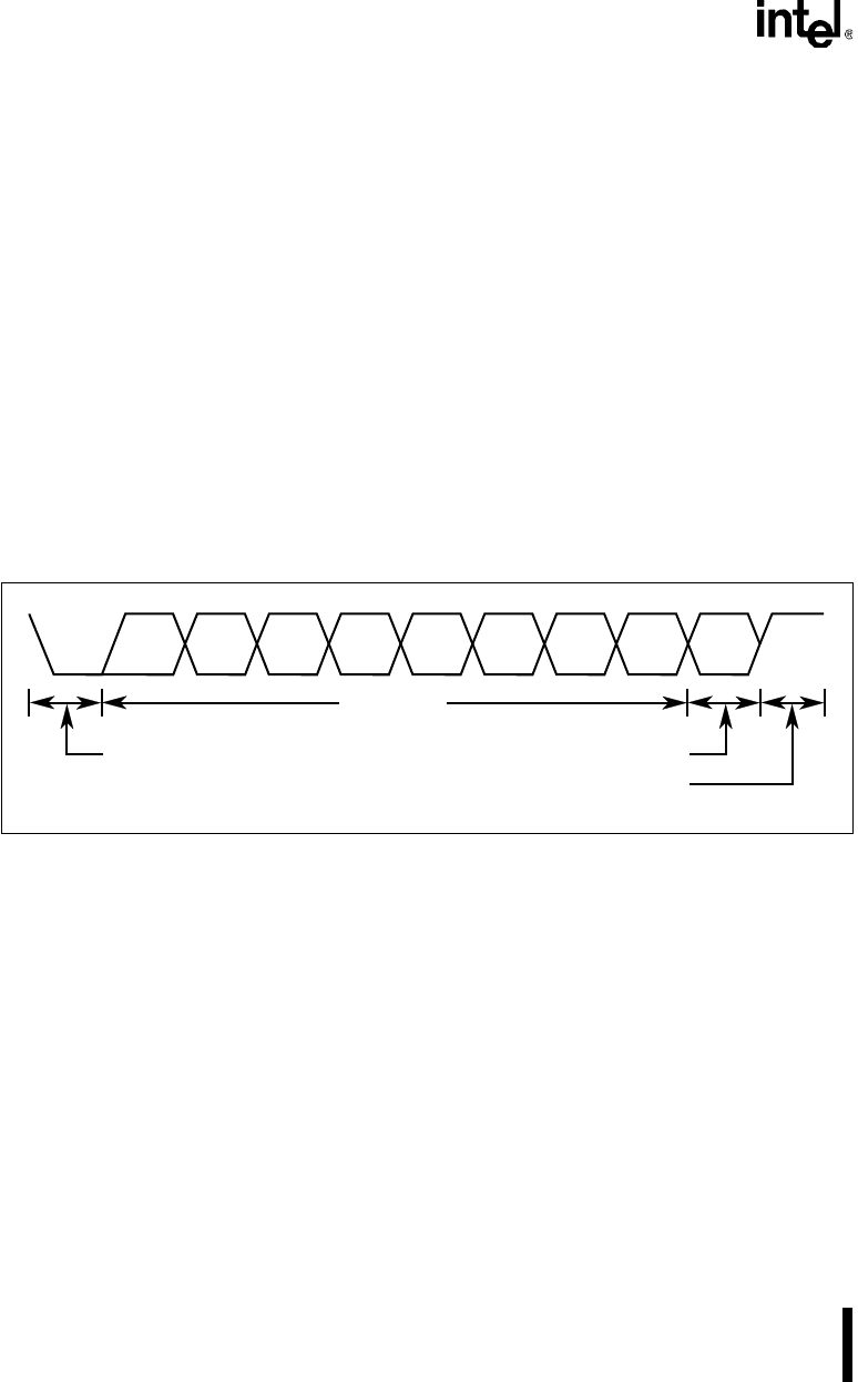
• Mode 1. Mode 1 is a full-duplex, asynchronous mode. The data frame (Figure 10-4)
consists of 10 bits: one start bit, eight data bits, and one stop bit. Serial data is transmitted
on the TXD pin and received on the RXD pin. When a message is received, the stop bit is
read in the RB8 bit in the SCON register. The baud rate is generated by overflow of timer 1
or timer 2 (see section 10.6, “Baud Rates”).
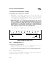
• Modes 2 and 3. Modes 2 and 3 are full-duplex, asynchronous modes. The data frame
(Figure 10-4) consists of 11 bits: one start bit, eight data bits (transmitted and received LSB
first), one programmable ninth data bit, and one stop bit. Serial data is transmitted on the
TXD pin and received on the RXD pin. On receive, the ninth bit is read from the RB8 bit in
the SCON register. On transmit, the ninth data bit is written to the TB8 bit in the SCON
register. Alternatively, you can use the ninth bit as a command/data flag.
— In mode 2, the baud rate is programmable to 1/32 or 1/64 of the oscillator frequency.
— In mode 3, the baud rate is generated by overflow of timer 1 or timer 2.
Figure 10-4. Data Frame (Modes 1, 2, and 3)
10.2.2.1 Transmission (Modes 1, 2, 3)
Follow these steps to initiate a transmission:
1. Write to the SCON register. Select the mode with the SM0 and SM1 bits, and clear the
REN bit. For modes 2 and 3, also write the ninth bit to the TB8 bit.
2. Write the byte to be transmitted to the SBUF register. This write starts the transmission.
10.2.2.2 Reception (Modes 1, 2, 3)
To prepare for a reception, set the REN bit in the SCON register. The actual reception is then ini-
tiated by a detected high-to-low transition on the RXD pin.
D0
D7
D8
D1 D2 D3 D4 D5 D6
Stop Bit
Ninth Data Bit (Modes 2 and 3 only)Start Bit
Data Byte
A2261-01