


6-15
INTERRUPT SYSTEM
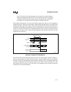
6.7.3 ISRs in Process
ISR execution proceeds until the RETI instruction is encountered. The RETI instruction informs
the processor that the interrupt routine is completed. The RETI instruction in the ISR pops PC
address bytes off the stack (as well as PSW1 for INTR = 1) and execution resumes at the suspend-
ed instruction stream.
NOTE
Some programs written for MCS 51 microcontrollers use RETI instead of RET
to return from a subroutine that is called by ACALL or LCALL (i.e., not an
interrupt service routine (ISR)). In the 8XC251Sx, this causes a compatibility
problem if INTR = 1 in configuration byte CONFIG1. In this case, the CPU
pushes four bytes (the three-byte PC and PSW1) onto the stack when the
routine is called and pops the same four bytes when the RETI is executed. In
contrast, RET pushes and pops only the lower two bytes of the PC. To
maintain compatibility, configure the 8XC251Sx with INTR = 0.
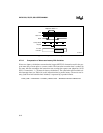
With the exception of TRAP, the start addresses of consecutive interrupt service routines are eight
bytes apart. If consecutive interrupts are used (IE0 and TF0, for example, or TF0 and IE1), the
first interrupt routine (if more than seven bytes long) must execute a jump to some other memory
location. This prevents overlap of the start address of the following interrupt routine.