


A-21
INSTRUCTION SET REFERENCE
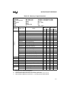
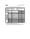
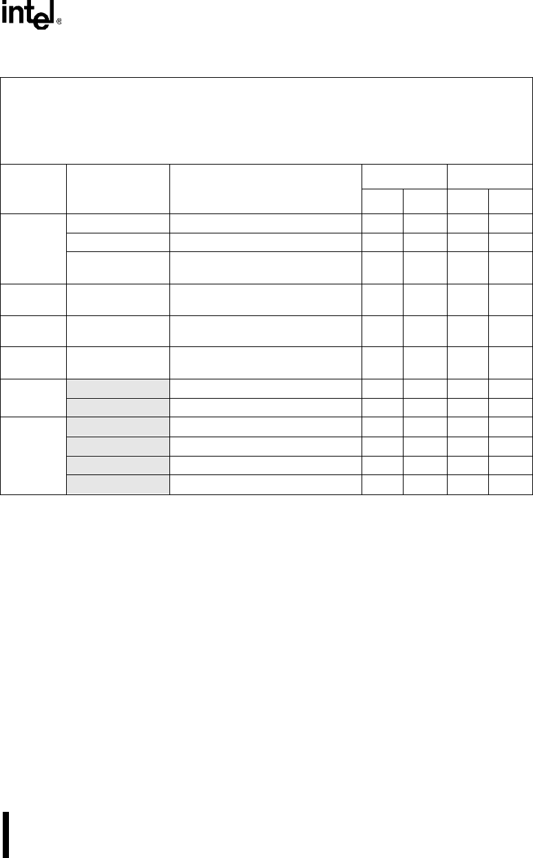
MOV
@WRj+dis16,WRj Word reg to Indir addr with disp (64K) 5 7 4 6
@DRk+dis24,Rm Byte reg to Indir addr with disp (16M) 5 7 4 6
@DRk+dis24,WRj Word reg to Indir addr with disp
(16M)
5847
MOVH
DRk(hi), #data16 16-bit immediate data into upper
word of dword reg
5342
MOVS WRj,Rm Byte reg to word reg with sign
extension
3221
MOVZ
WRj,Rm Byte reg to word reg with zeros
extension
3221
MOVC
A,@A+DPTR Code byte relative to DPTR to acc 1 6 1 6
A,@A+PC Code byte relative to PC to acc 1 6 1 6
MOVX
A,@Ri External mem (8-bit addr) to acc (4) 1 4 2 5
A,@DPTR External mem (16-bit addr) to acc (4) 1 5 1 5
@Ri,A Acc to external mem (8-bit addr) (4) 1 4 1 4
@DPTR,A Acc to external mem (16-bit addr) (4) 1 5 1 5
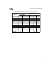
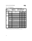
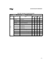
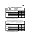
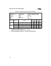
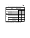
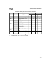
Table A-24. Summary of Move Instructions (Continued)
Move (2) MOV <dest>,<src> destination ← src opnd
Move with Sign Extension MOVS <dest>,<src> destination ← src opnd with sign extend
Move with Zero Extension MOVZ <dest>,<src> destination ← src opnd with zero extend
Move Code Byte MOVC <dest>,<src> A ← code byte
Move to External Mem MOVX <dest>,<src> external mem ← (A)
Move from External Mem MOVX <dest>,<src> A ← source opnd in external mem
Mnemonic <dest>,<src> Notes
Binary Mode Source Mode
Bytes States Bytes States
NOTES:
1. A shaded cell denotes an instruction in the MCS
®
51 architecture.
2. Instructions that move bits are in Table A-26 on page A-23.
3. If this instruction addresses an I/O port (P
x
,
x
= 0–3), add 1 to the number of states.
4. External memory addressed by instructions in the MCS 51 architecture is in the region specified by
DPXL (reset value = 01H). See section 3.1.1, “Compatibility with the MCS® 51 Architecture.”